Abstract : List of specifications for UST_1 : vacuum vessel ; number of coils, coil shape and structure ; properties of the magnetic confinement: plasma size, ripple, Iota, magnetic well, % of trapped particles; heating, Te and other details are shown.
The final choice was a modular two field periods (m=2) stellarator.
A few optimizations are done in the case m=3 but SimPIMF gave mediocre results. Because some compact stellartors like QPS and MHH2 are m=2 devices and aditionally because SimPIMF could easily obtain low ripple results and low proportion of trapped particles for the option m=2 and not for the case m=3, the alternative m=2 was chosen.
The shape of the coils is optimized for minimum ripple and maximum plasma size. Proportion of trapped particles is simulated later. The process is described in [1] and [8]
The specifications of the device are shown in the next table. The data comes from several pages in this web.
Some contractions used in the table:
G. 1 = See Graph 1 in this page
Ref. = Reference to understand the concept cited. I some cases the particular calculation in the refernce is not the same as here.
A) B) .. . = See the chapter in this page
calcul. = calculated or calculation.
improv. = improving
rough = rough analysis and calculation
Design 2m12C-15120811
| Ref. | Status | ||
| Vacuum Vessel | Built, tested | ||
| Major radius | 11.92 cm | ||
| Minor radius | 3.9 cm | ||
| Material | Copper | ||
| Shape | Circular, poloidally & tor. | ||
| Vacuum system | Mechanical + diff pump. | [4] | Built, improv |
| Coils | [1] | Trying | |
| Type | Modular coils | G. 1 | |
| Number (3 different shapes) | 12 | G. 1 | |
| Periods | m=2 | ||
| Turns per coil | 6 | ||
| Parameters of shape |
1.45 ; 1.2 ; 0.8 ; 1.1 |
[1], A) | Calcul. |
| Winding pack | 0.6 x 0.9 cm | ||
| Structure | 1 double pancake per coil | ||
| Case (being tested) | plaster? | Trying | |
| Winding surface | Circular pol. & tor. Diam 10.8cm | ||
| Power supplies | 24Kw See B) | [3], B) | Tested |
| Magnetic field | Basic calcul. | ||
| Radius of magnetic axis (on X+) | 0.112 | A) | |
| B on mag. axis(on X+) | 0.0893 T | ||
| B at mag. axis + 1.0cm | 0.081 T | ||
| B needed ECH(2.45GHz) | 0.0875 T | [2] | |
| Plasma radius, averaged | 1.68 cm | A) | |
| Current in each coil | 4190 A-turn | A) | |
| Ripple on axis | 1.2% | A) | |
| Averaged ripple | 14% | A) | |
| Magnetic well | Yes | A) | |
| Iota | 0.25 - 0.23 Decreasing | A) | |
| Plasma. Heating | Rough | ||
| ECH | 2.45 GHz | [2] | |
| Power ECH | 2 x 800 W | [2] | |
| Cut-off density | 1.3 x 10¹⁷ m-3 | [2] | |
| Te. Electron Temperat. | ~2eV | [2] | |
| Plasma density | 1 x 10¹⁷ m-3 | [2] | |
| Energy confinement time (1/20 of ISS04) | ~0.3 microsec. | [2] | |
A) Calculations for the coil configuration 2m12C-15120811
The process in [1] is repeated for 12 and 8 coils and some other calculations are done for the optimum case. Some concepts used here are described in [1].
A low value of ripple in the
calculation with 8 modular coils was impossible to obtain. The magnetic
ripple due to the separation of coils cannot be reduced significantly on
this particular winding surface and this specific method of optimization.
However Farrokh Najmabadi considered an alternative with 8 modular coils for
MHH2 [5]. Here the best averaged ripple is 25% and the maximum plasma
diameter (on X+ axis) is only 3.0cm. The 8 coils alternative was rejected.
All calculations are vacuum calculations without plasma pressure effect.
Number of coils = 12 ; m=2
Modular coils current = 3525A-turn (4190 A-turn is the scaled value to obtain the necessary |B|)
In the last run of optimization the intervals were : Pitch 1 = [1.25 , 1.75] Pitch 2 = [1, 1.5] Pitch 3 = [0.5, 1] Pitch 4 = [1, 1.5]
1296 different structures analysed.
Torsion is 1.3333 in all cases.
The best choice according to the radius of the last closed magnetic surface and low magnetic ripple was :
Pitch 1 = 1.45
Pitch 2 = 1.2
Pitch 3 = 0.8
Pitch 3 = 1.1
Similar parameters also give good confinement, therefore the result could still be slightly improved.
Graph 1 is the representation of the best coils which are denoted as "2m12C-15120811" . The plasma displayed in the vessel is the surface created by the trajectory of one electron at a middle location in the plasma. More simulations can be seen in [1] for the case of 16 modular coils.
Iota and Magnetic Well profiles
SimPIMF v2.2 adds a module to obtain Iota profiles and magnetic well profiles. It was used for a first test to know if the low ripple configuration has, at least, a magnetic well and an acceptable Iota profile. Graphs and more results will appear in a next page.
The calculation was done under the next conditions:
Step of time = 0.1 nSecond
Number of particles:
21 for the calculation of plasma size and averaged ripple. 200 KSteps.
41 for the profile of the magnetic well 1MStep
1 for Iota . 2 MSteps
Iota profile
The Iota profile in vacuum has an inverted configuration, with small shear, similar to W7-AS with Beta = 0.7% . It is not clear if this is a satisfactory feature for the confinement. Moreover the new code needs further test.
The values of Iota on some surfaces are: ( + x cm is on X+ coordinate)
Iota axis = No Data ; Ripple = 2.1%.
Iota axis + 0.5 cm = No Data ; Ripple =5.6%
Iota axis + 1.0 cm = 0.253 Ripple = 10%
Iota axis + 1.5 cm = 0.25 Ripple = 16%
Iota axis + 2.0 cm = 0.23 Ripple = 24%
A finner optimization will exclude the value 0.25 = 1/4 rational surface. The gaps 0.243-0.25 or 0.25-258 without low number rational surfaces might be tested. The next gap is around 0.333
Averaged ripple = 14%
(with ~21 particles for a plasma of 4.7 cm of diameter)
Plasma Size
Plasma Size = 4.7 cm on X+ coordinate
Averaged plasma diameter : aprox. 3.4 cm (several measurements on the graphic representation)
Magnetic Well
The specific volume on the last closed surface is 7.44 . On the magnetic axis it is 8.13 . This implies stable confinement [6]. Magnetic well depth at last closed surface = 7.4% . Some difficults still remain in the complete understanding of this concept, more when some incoherence has been found in different books and publications. Besides the code needs a better test.
Graphs and more results will appear in a next page.
Trapped particles
The method is explained in [2] and other pages.
1000 electrons are simulated , 200KSteps. It lasted 23 minutes.
The particles are thrown randomly in a toroidal volume of a particular radius.
Radius = 5 mm . This case is calculted only
to compare with the results in [8] . % of trapped particles = 19% . Less than in the studied classical stellarators.
Radius = 10 mm. % of trapped particles = 27.7%
Value relatively low in comparison with the information from [7]
B) Power supplies
A condition already stated in [3] is still considered now. As a result, low voltage and high currents are sought but the copper wire becomes too thick to be wound. Moreover, the precision of the magnetic field decreases when the number of turns reduces. This happens due to the difficulty in compensating the crossover effects and the perturbation at the end of the wire in the winding pack. This perturbation can be perfectly simulated with SimPIMF but has not been done yet.
A middle point is taken. A conductor of 3mm in diameter is chosen and ordered.
Two main options seem to be the best.
1) 12 coils in series. It results a little excessive resistance for normal batteries. The perfect match of impedance for maximum power is not achieved. However this is the more equilibrated method since the current is always the same in any coil. 6 batteries are necessary and max 78V will be in the system. 24Kw are dissipated in the coils. Increment of adiabatic coils in a pulse of 1sec = 40ºK.
Only one battery is considered for the magnetic field mapping.
2) 4 identical coils in series . 3 groups of coils in parallel . This option has a perfect match (considering the lower internal resistance in [3]) and require only 3 batteries. 13V will be the maximum voltage in the system. A similar option is chosen in W7-X but the power supplies are extremely perfect there.
Cost
Because the cost of the power supplies for the coils is the major limiting factor in UST_1 (and in other stellarators) this issue will be considered only after some results were achieved with batteries. The use of supercondensers, idea proposed by J.A. , CIEMAT, have not been analysed or tested yet.
Further developments
Some months are considered to develop, order, assembly, built and start all the systems.
References
[1] to [4], [8] : Vicente M. Queral . See “Past R&D" in this web
[1] "Optimization of modular coils by means of SimPIMF v2.1"
[2] "Energy confinement time and estimation of the heating system in UST_1"
[3] "1200A test Pulse and set-up of Data Acquisition"
[4] "First run of the diffusion pump. History of the vacuum progress"
[8] "Optimization of UST_1 for m=3, 4 and 5 periods. Minimization of trapped particles and ripple"
______
[5] "Exploration of Compact Stellarators as Power Plants" Farrokh Najmabadi , 16th ANS TOFE
[6] "Stellarator and heliotron devices", Masahiro Wakatami, pg 14
[7] "Electron cyclotron heating and current drive in the TJ-II
stellarator"
, V Tribaldos, J A Jimenez,
et al .
Plasma Phys. Control. Fusion 40 (1998)
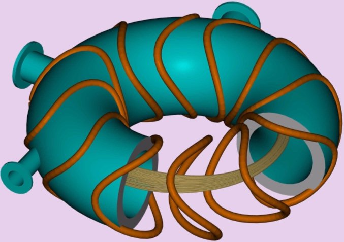
Graph 1 Representation of the modular coils (redish), magnetic surface (orbit in orange) and vaccum vessel
Graph 1 Representation of the modular coils (redish), magnetic surface (orbit in orange) and vaccum vessel
Last Update 22-02-2006