Abstract : An experiment with pulses of current is described. The pulses are produced by only one unit of power supply. A simple system of data acquisition is set-up for this experience and for the future diagnostics and control. The objective of these pulses is to asses the capability of batteries to produce high current pulses of moderate length, about 1 second.
Objective
Find out the internal resistance of the battery and the behaviour at any work regime. The design of the coils will try to match the internal resistance of the batteries. The possibility of two batteries in parallel or 4 batteries in series-parallel will be also analysed.
Experimental system
A normal automobile battery is chosen as a first test of the performance of normal batteries to produce pulses of various kA from a few tenths of seconds up to 1 second.
Batteries can produce longer pulses than condensers at the same cost but the current is lower. However a longer pulse seems better for a small stellarator with an educative aim because diagnostics and control are far more expensive when the length of the pulse is reduced to milliseconds. Additionally one idea is to build resistive coils in order to work in a similar manner as superconductor coils. Hence a high current and the minimum voltage is required.
The battery is connected to
a steel wire (in general 3 parallel wires) that acts as a power resistor,
R1, see Graph 1. Different values of resistance have been experimented. A
final measurement without the steel wire is taken to test the battery in
short-circuit. In this case only the 3m length Cu conductor is present.
A high power contactor, C1, 3x150A nominal current, is used. About 3 to 5
times the nominal current can be supposed for a pulse less than 1 second. A
kind of manual safety section switch, S, is installed in series with the
circuit. Fuses or other safety circuit-breakers are not used due to the
diversity of experimental situations.
The current is obtained by
measuring the drop voltage in R1 that is the voltage Udc and knowing the
resistance as an input. The resistor R1 is calibrated in Ohm/metre from
measuring and it has enough heat dissipation for the length of the pulse.
Several measurements are taken with different values of R1.
Data acquisition
A simple system based on PC
is being developed. At the moment only one A/D card capable of 4
differential inputs is used. One interface box with quality connectors,
several voltage dividers and coaxial cables are coupled to the card.
Protection against overvoltage is not implemented yet. The same A/D card,
from the Berstron brand, has 5 digital inputs. The system is fully
extensible to several A/D cards and hundreds of digital I/O. Therefore it
should be useful for the control of the stellarator and the data acquisition
system.
This A/D card is specially featured for sensors using a Wheatstone bridge,
thermocouple pressure gauges, temperature sensors, etc. It has 2mV of full
scale sensitivity, resolution of 12 bits and max. 50 Ksamples/s.
Results
Some results from the
measurements are shown in Graph 2. The internal resistance of the battery is
calculated supposing an ideal power supply of about 12.8V in series with a
resistor. The current in the circuit is measured using the method described
above and the voltage Uab during the pulse is known from the A/D card or
from a multimeter before the A/D system were
operational. The internal resistance
decreases up to 0.006 Ohm at the maximum current.
The maximum current obtained was 1226 A. However this current will not be
reached in the coils of the stellarator if only one battery
is used..
The resistivity of the steel wire was
measured resulting 1.84 x 10⁻⁷ Ohm-m at 30 ºC. The error in this measuring
is high, even 10%, due to the low resolution of the multimeter at this
range. This measurement will be improved. Other DC current
probes will be tested to obtain redundant data.
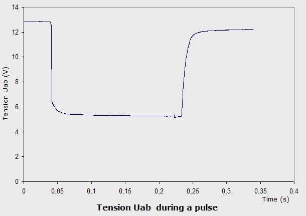
Graph 3 is the voltage
drop at the power supply during one pulse
produced using 0.5m of steel wire, R1~=0.0086 Ohm.
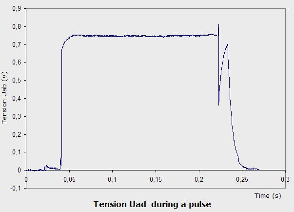
Graph 4 is the voltage at the resistor
R1 which is equivalent to the future coils. The power
dissipated has a direct relation with the magnetic flux density
in the torus. Some losses are observed in the contactor C1 and the Cu lead.
495A and 2100W of dissipated power were measured. The increase in the
voltage Udc with the time is mainly
due to the heating of the resistor. The final
switching overvoltage will be controlled in the stellarator
because the
inductance is much higher than here.
Graph 5 is the result of the
short-circuit pulse. Voltage Uad is measured in this case. There is no steel
wire. Voltage Uab drops to less than 6V. In Graph 6 some instabilities
occurs after opening the circuit. This will be analysed. Certainly this is
an extreme pulse that will not happen in normal operation of the
stellarator. A current of 1226 A and 4900W in the Cu cable were obtained
with only one battery.
Further developments
Improvement of the data
acquisition system is necessary, more I/O lines, higher accuracy, less
interferences and better calibration. The design of the adequate system power
supplies-coils will be carried out. Improve the performance of the
electrical operations, discharge resistor, etc.
References
None
Graph 6 . Voltage Uad during the pulse.
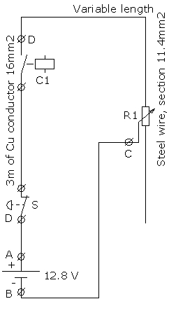
Graph 1. Electrical layout of the experiment
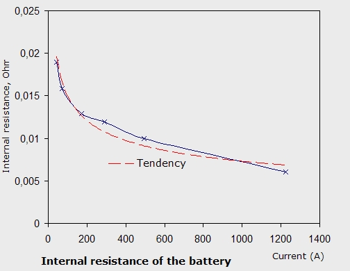
Graph 2 . Internal resistance of the tested battery.
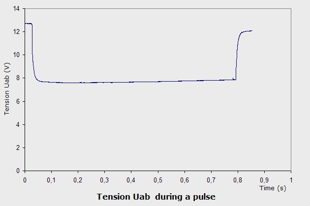
Graph 3 . Voltage Uab during a pulse.
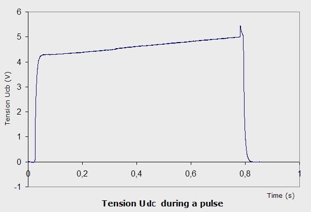
Graph 4 . Voltage Udc during a pulse.
Graph 5 . Voltage Uab along the pulse.
Graph 6 . Voltage Uad along the pulse.
Last Update 29-07-2005