Abstract : The progress in the achieved vacuum level will be recorded in this page. The first milestone has been the start-up of the diffusion pump.
Objective
Achieve a low vacuum level with limited economical resources. An acceptable vacuum level for a first stage of the system was defined as 10-2 Pa [1].
Experimental system
The experimental system is continuously evolving so in each experiment the conditions of the system are briefly described. In each case the base of the design is Graph 2, which is explained in [1].
Present status of the vacuum system
Some additional information appears in [1].
On 11 October 2005 the status of the vacuum system is:
- The diffusion pump is operating. It is using vacuum mechanical
pump oil to preserve the DC-704 oil, quite more expensive, until the system
is tested and well understood.
- Most of the fittings are silver soldered. Some
of them
will be replaced by
commercial fittings in the future.
- The Varian UHV vacuum valve, electrically
operated, is not installed because there is not information about the
electrical connections yet (it is an obsolete model)
- The ebay second-hand mechanical pump, a Pfeiffer DUO 000A is
luckily in good state and the performance at the moment is passable. Now it
is working with normal A/C vacuum oil; the specifications for the oil and
maintenance might be found. It is also an old model.
- The system from the ball valve to the vacuum mock-up port leaks
at a rate around 5 x 10⁻⁶ Pa/m3s . This includes real and
virtual leaks. Virtual leaks seem that are decreasing,
partly because on 27 September fittings
were intensely cleaned with acetone and alcohol.
Some experiences were done using a loaned A/C mechanical pump before the Pfeiffer arrived. The results were poor due to the low pumping speed and the low conductance of the fittings.
Results
Graph 1, Experience A .
Date : 10-10-05 . Conditions : Only the TC is fitted at the inlet of the Pfeiffer vacuum pump. A silicone tube of 10cm, 8mm diameter is the only vacuum volume. This curve was obtain after about 2 hours of degassing the new vacuum oil. Two other graphs, not shown here, prove the improvement of performance with the working time of the Pfeiffer pump.
Graph 1, Experience B .
Date : 10-10-05 . Conditions : As a first try, a 20 cm, 8mm interior diameter silicone tube were used from the Pfeiffer to the ball valve. Otherwise the fittings need to be silver soldered. Conductance were very low so the recommended back-up pump, about 4cfm, was not fulfilled by far. The result was high base pressure, about 30 Pa and continuous oscillations of the pressure when the diffusion pump was trying to start. It is supposed that the pressure at the foreline increased over the correct foreline pressure (less than 0.2 - 0.6 Torr depending on models) and thus finishing the pumping of the diffusion pump [2].
Graph 1, Experience C .
Date : 11-10-05 . Conditions : Home-made fittings were built for the Pfeiffer pump (the flange of the Pfeiffer was unknown until its reception). Their conductance is correct and now the limiting point is the ball valve. The oil in the diffusion pump is mechanical oil. The real assembly appears in Photo 1.
Finally the diffusion pump started although only for little less than two minutes.
The reason for the return to the instabilities is not clear. An overheating of the pump for this type of oil might be the reason.
Only 1 Pa was achieved. However the vapour pressure of the mechanical pump oil is 10-2 to 10-3 Pa so with difficult less than 1 Pa is achievable.
The replacement of oils and minor improvements may reasonably result in 10-2 Pa.
Further developments
The second TC has to be installed to know the pressure at the foreline. The oils for the two pumps need to be changed to achieve the maximum performance.
References
[1] " Vacuum system in UST_1 " , Vicente M. Queral. See "List of all past R&D" in this web.
[2] "A user's guide to Vacuum Technology", John F. O'Hanlon ; Wiley Interscience, Third edition, pg 219.
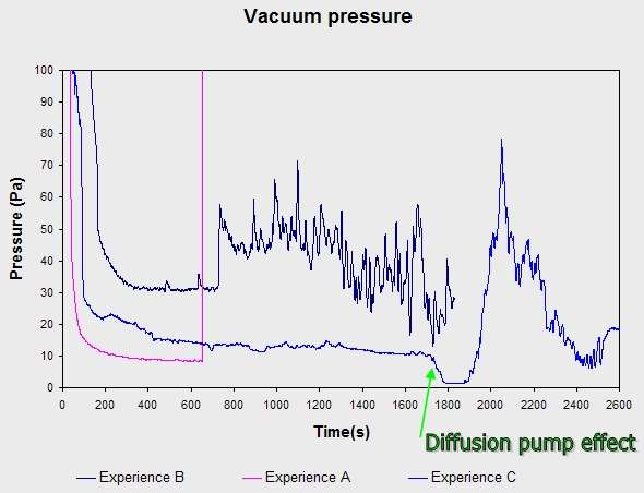
Graph 1. Evolution of the vaccum pressure for some experiments
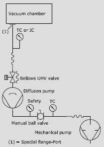
Graph 2. Vacuum layout of the experiment
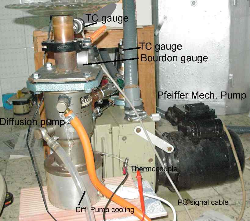
Photo 1. Assemble of the present vacuum system [this is not the correct photo, It will be changed]
Graph 1. Evolution of the vaccum pressure for some experiments
Last Update 11-10-2005