Abstract : The status of the vacuum vessel on February 2006 and some later improvemens are shown. Lower pressure and graphs of outgassing.
Design
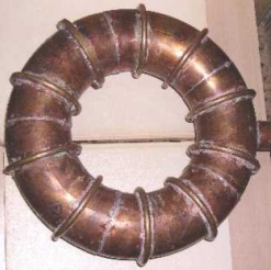
During the development of the porcelain vacuum vessel [1] and due to the difficulties found, a copper vacuum vessel was developed. The chamber is made from standard copper gutter of 0.8mm wall. This thickness is less than the recommendation in Dolan and it could be calculated by finite elements as in [2]. 10 brass rings calculated to withstand 1/2 of the total force on the proportional area corresponding to the ring, applied on one side of the ring are soldered on the torus. Rings are made of brass rod of 8mm diameter. See Photo 1.
At this moment two prototypes of porcelain vacuum vessel are successfully built but the copper device is the present line of development.
Outgassing
The vacuum vessel made from 5 pieces of copper gutter has some disadvantages and advantages with respect to a porcelain one.
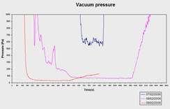
One disadvantage are the internal virtual leaks from the joints that are impossible to avoid or to remove due to the small size of the device, so the outgassing seemed to be and is notable high and it decreases slowly as can be seen in Graph 1. The graph shows the evolution of the outgassing (the increasing part of the magenta and red lines). The blue line at the level of 600Pa was the result after the first connection of the mechanical pump. The other two lines are taken in the days specified in the graph using only the mechanical pump.
After 3 days of outgassing without baking the outgassing was 6x10⁻⁴Pa m3/s.
Because of this disadvantage a heater will be useful for a low temperature baking in order to speed up the outgassing rate.
Lower pressure
Under the last conditions the minimum pressure was under 0.5Pa. The value will be exactly know when the recently two units of Edwards Active Inverted Magnetron or Cold Cathode gauges are installed. They are ebay items without warranty, manuals or connectors so extra difficulties will appear.
Added on 11-5-2006:
The Edwards Active Inverted Magnetron is installed and working. There were some difficulties to obtain the manual of the gauge from the Spanish representative of BOC Edwards, but the central offices in UK were very kind to help me.
In the fist moment (the vacuum vessel has far less outgassing after 3 days of outgassing), the pressure in the system without the vacuum vessel dropped up to 5.5 x 10⁻³ Pa. So the objective of 10-2 Pa is achieved. The vacuum vessel after 3 days of outgassing (or after some baking) have similar outgassing rate than this present experience, so 10-2 Pa will be possible.
A new and more demanding objective is established here, to achieve 10-3 Pa in the vacuum vessel after only one day of outgassing. Some improvements are possible, each one with a particular cost:
- Change the oil of the diffusion pump, by now DC-704, and install DC-705 or fluorocarbon one.
- Change the high vacuum valve from a bellows Varian valve to a gate valve and increase the piping to NW50 size.
- Clean the vacuum vessel with some unknown process adequate for copper and after that fill the chamber with nitrogen when it is opened.
End of added text
Added on 19-07-2006:
* NW50 fittings are installed and the Varian vacuum valve and NW40 fittings are removed. The conductance has been increased to achieve improved vacuum in spite of the high outgassing and small leaks. This has been accurately calculated. AIM-S reached 8.90V in the vacuum vessel after 15 minutes. The pressure is 9 x 10⁻³ Pa .So the objective of 10-2 Pa is really achieved now.
* A new low cost ebay Lam Tylan General capacitance gauge is added to the system. The item was out of order but a careful search revealed a damaged protection diode.
* A correct calibration of the TC gauge at high pressure is done by means of Tylan gauge and at low pressure using the AIM-S magnetron.
* Some overheating and oil spillage has been observed on the Pfeiffer roughing pump. It difficults long sessions of outgassing.
* Because the "ultimate" pressure without vacuum vessel was 5.5 x 10⁻³ Pa a new analysis of the system is necessary if lower vacuum is required.
- The mechanical pump reaches 4 Pa with difficult so it could influence in the ultimate pressure of the diffusion.
- DC-704 oil might be contaminated by remains of the mechanical oil introduced for the first test
- DC 704 has a vapour pressure at 25ºC = 1 x 10⁻⁷ Torr = 1.3x10⁻⁵ Pa that will be higher at the warm top of the diffusion pump.
- In one particular diffusion pump using DC-704, the pumping speed start to decrease at 10-6 mbar = 10-4 Pa. So this is an order of magnitude of the limits of the present system
End of added text
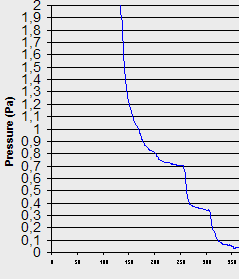
At present the calibration of the TC gauge is not possible because it is not clear if the vacuum is under 0.1Pa what is the condition of calibration of the TC gauge. The results in Graph 2 show 3 possible values taken at 17mA , 17.5mA and 18mA of current in the heater of the TC. The correct value will be between 0.4 and 0.05Pa because usually the 1518 TC has this range of heater currents as point of calibration.
The vacuum is enough for a first observation of the quality of the magnetic surfaces and magnetic axis using excitation of the remaining air. Some information is available about past experiences of this type.
10-2 Pa was stated as the first objective in the vacuum system so the objective is not fulfilled yet. However it seems that could be reached.
Further developments
The inverted magnetrons need to be installed. Some new vacuum flanges, bellows and clamps are being shipped and will be installed.
References
[1] "Vacuum vessel for UST_1. Status and improvements" Vicente Queral , See "List of all past R&D" in this web.
[2] "FE stress analysis for a
first outline of the vacuum vessel of UST_1" . Vicente Queral ,
See "List
of all
past R&D"
in this web.
Photo 1 . Copper vacuum vessel with reinforcements .
Graph 1 . Process of outgassing in the vacuum vessel of Photo 1

Graph 2 . Pressure inside the vacuum vessel after the diffusion pump is connected. The variations are the results for 3 different currents in the TC heater
Date of publication 20-02-2006 . Additions on 11-5-2006 and 19-07-2006

