Abstract : Photos and results of the preliminary tests of the windings for the modular coils are shown
Present state
The device to create grooves for modular coils is nearly finished and a first test groove has been mechanised. A patent has been applied for the device so it will be described in a next future.
6 turns per coil, 12 coils and a groove of 6mm width and 9mm depth is the standard design [1].
Here some additional trials are done to know if other alternatives are feasible.
7mm2 solid circular wire
Circular wire of 3mm diameter was tested but cannot be accurately wound into the groove partially because the groove is made of plaster which is too soft to withstand the necessary pressure to conform the coil. This is the ideal option because the copper fraction is high.
4 wires of diameter 1.5mm were tried by they tend to overlap and move so it is no an option by now.
6mm2 special flexible conductor
Another option is the use of flexible conductors made in-site. Very compact standard conductors might be found in the market. For example two companies, Nu-Core and Electro-Ma, were interested in compact flexible conductors for NCSX [2]. However it is not affordable for this semi-professional stellarator that lacks of any financial support. A first try was done to wind a 6mm2 conductor wrapped in tape, Photo 2, but further research must be done. The ideal 3mm wire has about 7mm2 of section so the difference is small. A square section of flexible conductor will also be tested.
[Added on 27-02-06] The use of a heatshrink tube is tested and the result is satisfactory. The tube is 0.3mm width and after shrink a little more. The result is shown in Photo 2.1 in a 7mm width groove.
10mm2 standard flexible conductor
A 10mm2 and only one turn is tested. It fits accurately in the groove however the innacuracies of the field due to the only turn and the leads difficult this alternative. See Photo 5.
2.5mm2 standard flexible conductor
In Photo 3 the test is shown. The groove should be 7mm width to wind this conductor and 10.5 depth so it could not be wound in the 6mm groove. The section of copper is small and only the field mapping experiment, at lower current, may be tested.
[Added on 27-02-06] The conductor fits correctly In a 7mm groove.
1.5mm2 standard flexible conductor
Photo 1 displays the result of the winding. The conductor is double and fits exactly in the groove. However the section is extremely small. A first crossover is tested, photo 4. The possibilities of crossover are the common ones. Some innovations are planned to smooth the distortions because of the low number of turns in the coils of UST_1.
Further developments
Test more conductors, wrap a compact flexible conductor, decide the width of the groove.
References
[1] "Technical specifications of UST_1" Vicente Queral , See "List of all past R&D" in this web.
[2] "Status
of Non-Axisymmetric Coils Study" .
NCSX Project ,
Handouts for Project Workshop, Web

Photo 1 . 4 turns of 1.5mm2 conductor
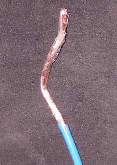
Photo 2 . Wrapped 6mm2 conductor.
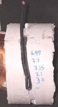
Photo 2.1 . Sleeved 6mm2 conductor in a 7mm width groove.
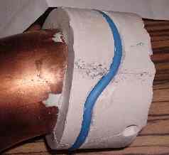
Photo 5 . 10mm2 standard flexible conductor . Ony 1 or 2 turns can be wound.
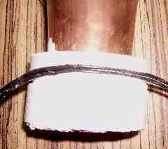
Photo 3 . 2 partial turns of 2.5mm2 standard flexible conductor
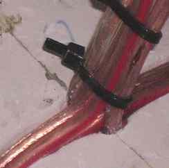
Photo 4
. Crossover option
Last Update 20-02-2006