Abstract : Description and photos of the process and difficulties to finally achieve the mechanization of the first modular coil for UST_1.
Present state
In April 2006 the first modular coil was finally mechanised by means of the "Device to mechanise modular cols" [1]. The rest of the coils will be manufactured soon. The manufacture of each groove lasts about 1.5 hours. There are 12 grooves corresponding to 12 coils.
Brief description of the elements and process
1) Rough surface
The origin is a rough surface of plaster, Photo 1, conformed in to halves in a polystyrene mould. The toroidal shape of the mould is created by a hot wire adapted to the same device to mechanise modular coils.
2) More accurate toroidal surface
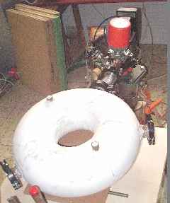
The rough surface is mechanised using the device, a special type of milling machine working on toroidal coordinates, to obtain a reasonable uniform surface. The layer of plaster is 15mm thick at least. Accuracy is not necessary here but it is +-0.2mm because the surfaces are poloidally and toroidally circular like the coordinates of the milling machine [1]. The finished surface is shown in Photo 2. Unfortunately the internal part of the torus has important irregularities due to a lack of plaster (the mould produced a lack of plaster in those areas instead of excess). This does not produce any error on the grooves, it is only a visual imperfection. The torus is under vacuum in Photo 2 to test again possible new leaks after mechanization.
3) Accurate grooves and conductor
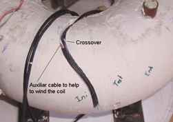
A 6mm2 sleeved flexible conductor is chosen, see [2]. The sleeved conductor is fabricated in site from a commercial flexible conductor whose isolation is removed and a thinner shrinkable isolation is added. The objective is to increase the space factor (ratio copper/ total section). A groove of 7mm width is necessary for a double pancake winding pack. The external diameter of the conductor is about 3.5mm. Each pair of conductors is compressed in the groove to easier wind the coil and to fix and better position the winding pack. The first layer of the double pancake is displayed in Photo 3. The accuracy of positioning and systematic errors are relatively small as described below. The small oscillations seen in the Photo 3 are caused by the semi-automatic mechanization but they are random errors at both sides of the theoretical curve. The conductor, which has a diameter much bigger than the oscillations, is barely affected by these errors.
The groove is 12.5mm deep but only 10.2mm will be occupied by the conductor. The rest could be used if the coils are expanded.
Errors in the mechanization
The milling machine has been accurately measured and adjusted to achieve relatively high precision even in this low cost apparatus.
Systematic errors
Systematic errors come from the inaccuracies in positioning, verticality/horizontality of guides and distortion of elements.
- The maximum measured error in verticality of the fixed ring is 0.2mm at the area near the centre of the torus.
- The error in the position of the major radius of the torus is less than 0.1mm.
- The error in the minor radius of the winding surface might be less than 0.2mm but it is difficult to prove.
- There is an error of 0.3º in the position of the poloidal angle because one piece of the device that was a prototype was not substituted by a new improved one.
- The circular ring of mechanization formed by two half-rings cut from a lathed ring is deformed 0.2mm (the vertical diameter is 0.2mm bigger than the horizontal diameter). The error was as high as 0.6mm before the adjustment and the reason of this deviation is not clear. This piece should be accurate up to 0.1mm without any adjustment. This error is partially cancelled by the mechanism.
* There are no assembling errors because mechanization and positioning is the same process in this method of building coils and the torus can remain on the same legs during the whole mechanization. This property might be important for low cost university stellarators.
Random
Random errors mainly come from the semi-automatic manufacture of the grooves.
- Two or three oscillations per coil of the type shown in Photo 3 are as big as 0.5mm in the manufactured coil. However these errors are nearly cancelled by the average and the stiffness of the conductor. There is no accumulation of errors or permanent deviations (one deviation in one direction is necessarily opposite 1 or 2 millimetres later). These errors could be reduced to +-0.2 adding a PC controlled system with motors and synchronous belts or gears.
- There is a small play less than 0.05mm at the central axis of the device .
- The play in the circular mobile guide is smaller than 0.2mm. Inaccuracies in the circular ring force a loose adjustment on the guide and cause some play.
Difficulties
The main difficulties have been the adjustment of the milling machine and the decision about the configuration of coils for the best confinement. However the confinement never will be satisfactory in UST_1 because of the extremely small size and because the coils do not have real 3D freedom -they are constrainted on a circular winding surface.
* The pieces of the device except for the ring are not mechanised by CNC so each element has to be accurately positioned with precision better than +-0.1mm. This require an iterative and slow process.
* The definition of the coils was changed several times as can be seen in this web.
The reasons for the changes among others were:
- At the beginning the code calculated inaccurately the plasma size, so the first sessions of optimization were useless.
- Later the minor radius of the winding pack was increased 3mm to allow an expansion layer of foam between the vacuum vessel and the plaster and to have more free space. This modification was very detrimental because the centre of the torus was significantly reduced because UST_1 is a relatively compact stellarator. The best new optimized results are slightly worse than the original, [3]. The fact of this important modification of properties was unknown before.
- Finally it was noticed that some of the best configuration of coils had overlapping coils. At first a visual inspection by CAD seemed enough but at the last check before mechanization an overlapping was noticed. Now the optimization code calculates the minimum distance between coils. The consequence was a degradation of the properties of the plasma in more than 10% in several properties (plasma size, magnetic well, Bmin) when the algorithm to avoid overlapping of coils was implemented. Some time was spent to try to find solutions of the same quality as before but it, logically in some sense, was impossible.
The process of optimization, even for this basic optimization, seemed endless. Luckily a final design has been decided and built.
Further developments
The rest of coils need to be manufactured and the quality of the magnetic field must be tested by field mapping. With this test, supposed satisfactory, the first stage of the UST_1 project will be finished.
References
[1] "Device to mechanise modular coils", Vicente Queral , See "List of all past R&D" in this web.
[2] "Test of modular coil windings" Vicente Queral , See "List of all past R&D" in this web.
[3] "Optimization of Iota, Iota profile, plasma size, Bmin and magnetic well" , Vicente Queral , See "List of all past R&D" in this web.
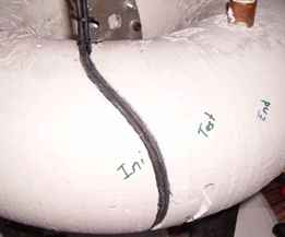
Photo 4 . The completed modular coil with 6 turns.
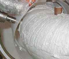
Photo 1 . Rough surface of plaster before amd during mechanization
Photo 2 . Finished toroidal external surface with medium accuracy mechanization. Under vacuum
Photo 3 . First layer of the double pancake
Photo 4 . The completed modular coil with 6 turns
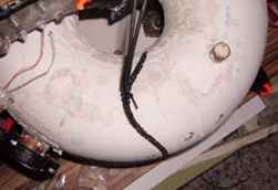
Photo 5 . The completed modular coil, top view
Date of publication 26-04-2006
