Abstract : Simulations of the standard configuration in CNT 'Columbia Nonneutral Torus' are carried out. Results are compared with the ones form CNT team so to further validate SimPIMF code. Iota profile, ripple, magnetic well depth, magnetic surfaces, islands, and rationals are calculated-simulated and analysed. The contrasted results from SimPIMF agree notable well with CNT team results. Magnetic well depth is negative and ripple is very high however CNT construction is simple and the cost low.
CNT, Columbia Nonneutral Torus, is an innovative stellarator in Columbia University mainly dedicated to the study of non-neutral plasmas.
Objectives :
* Further test SimPIMF code . If results from CNT team and from SimPIMF are similar it further validate the code.
* Better understand CNT style stellarators.and indirectly, understand Paul Moroz desings [1], that have some resemblance to CNT but with no interlocked coils and in general having a higher number of coils.
* Calculate important parameters, some of them only an order of magnitude, to contribute to the previous objective. Almost all results come from SimPIMF code.
- The objectives here are different from CNT ones. CNT is dedicated to non-nuetral plasmas at very low pressure so requirements for confinement are notable different from common stellarators.
Modellisation
The dimension and position of the coils are taken from [2], the current ratio in the coils TF/PF and the magnetic field at axis from [3]. Some simulations are carried out at zero drift but other with electrons at 100eV and drifts. to compare with the magnetic surfaces in [3] and [4].
SimPIMF code has been improved in minor functions.
- Organise the input data inorder to easily change from UST_1 model to CNT model or other models.
- A 'Method' to generate titled coils has been added. It is a general procedure that generates a parametric tilted coil in the place of a normal vertical TF coil, so designs style Paul Moroz [1] have been modelled (but not studied) as a test. CNT design is a model with 2 TF tilted coils at the correct locations.
Angle between IL and PF coils = 64º in this study.
Currents
A first try was done using the currents in [2] , IL =170 kA-turn and PF = 40.3 kA-turn but the magnetic surfaces were slightly different.
New data was found as a result of the study of this issue. In [3], current ratio TF/PF = Alpha = 3.64 and B=0.1T at axis.
In this model B=0.1 T on the magnetic axis on y+ axis (at the centre of the IL coils). Due to the high ripple in CNT, even on the magnetic axis, the value on x+ and y+ differs but it is only relevant in simulations with drifts.
Currents in the simulation are IL = 53299 A-turn PF = IL/ 3.6 = 14805 A-turn.
Magnetic axis and general view of the surfaces
The magnetic axis for a trajectory without drifts and alpha =3.64 is on x+ = 0.303 m .
The simulation of the magnetic axis is shown in Fig. 1
One external magnetic surface is presented in Fig. 2 .
which is similar to Fig. 3 in [2].
Ripple
Ripple in CNT is very high as could be supposed from the very small aspect ratio.
Ripple on each orbit is calculated as = (Bmax - Bmin) / (Bmax + Bmin)
- From SimPIMF, ripple at axis is = 0.28489 ~ 0.28 , very high for the magnetic axis. The reason seems to be the small number of TF coils, the limit of only two coils. In UST_1, 12 modular coils, the ripple on axis is only ~0.03 .
- Ripple = 0.69 on the surface represented in Fig. 1, near the edge at x+ = 170mm, also very high.
Approximate analytical ripple = epsilon = 1/ Aspect ratio = 1/ 1.5 = 0.666 . Both values are similar as it should be.
It is a notable negative issue for confinement for not optimised stellarators. Almost all the particles are trapped and they are direct losses at collisionless regime if they are not confined by radial electric fields.
Magnetic surfaces and comparison with other results
Magnetic surfaces are simulated and represented by SimPIMF code for the conditions defined above.
Two simulations are carried out.
1) The first simulation is accomplished with the same conditions as in [2] and [3] in order to compare with the Fig. 7 (b) in [4] that is the same as in [3]. So electrons are simulated at 100eV with drifts. Magnetic 'Grid' is 1/80 m = 12.5mm . The increment of x position is taken 13mm because it is similar to the separation between magnetic surfaces in Fig 7. in [4].
Result appear in Fig. 3 .
The images (Fig. 7 (b) in [4] and from SimPIMF) are superposed by joining the magnetic axis. The result is shown in Fig 4 . Both simulations agree notable well so it further validates SimPIMF code. Slightly different input conditions or some remaining deficiencies in SimPIMF might be the reason for the small deviations.
2) Finer simulation without drifts. Objective : Try to find the small islands that might remain in-between the wide separations among surfaces in the case 1). 250 surfaces are calculated-simulated, separated 1mm. 'Grid' = 1/80 and the simulation lasted 394 seconds.
Fig. 5 shows the result. Some new small islands appear which are analysed next.
Iota calculation and profiles
The fast calculation of Iota profile lasted 243 s and the accurate calculation 1813 s . The next results are taken from the accurate calculation, however they are quite similar.
An electron is thrown each 10mm on the x axis. In this model the romboedric magnetic surface is located at phi = toroidal angle = 0 while the bean shaped one is located at phi = 90º . Phi = 0 poloidal plane contains the x+ axis.
Iota profile is shown in Fig. 6 . It increases and the graph is similar to the result form the CNT team in [2]. However Iota near the axis is around 0.15 in Fig. 5 in [2] and about 0.12 in Fig. 6 from SimPIMF. The deviation might be caused by a different ratio alpha = IL current / PF current which is not stated in [2].
Rationals and islands
Islands from edge to centre :
(Value : approximate value of the rational
Calculated : value calculated by SimPIMF)
| Colour | Figure | Rational | Value | Calculated | |
| Blue | 3 | 1/4 = 2/8 | 0.25 | 0.249974 | |
| Green-Yellow | 3 | 2/9 | 0.2222... | 0.222282 | |
| Magenta | 5 | 1/5 =2/10 | 0.2 | 0.19952 | |
| No visible | 2/11 | 0.1818... | - | ||
| No visible | 1/6 | 0.1666... | - | ||
| Red (faint) | 5 | 1/7 | 0.142857.. | - | |
| Blue-Magenta | 5 | 1/8 =2/8 | 0.125 | - | |
| ... | ... |
Islands with n=1 (rational n/m) have another independent chain of islands that appear as a white hollow area in automatic SimPIMF simulations. Islands 2/11 and 1/6 could be distinguished but might be very small.
The size of the islands depends on magnetic field errors that are related up to certain degree with the size of the 'Grid'
Magnetic well
The specific volume has a minimum at the magnetic axis (24.14 u) and (29.23 u) near the edge so, following Wakatami and Dolan, the Magnetic Well Depth is negative and it is not optimum for confinement. MHD stability was not considered in CNT because of the extremely tenuous plasmas studied in nonneutral plasmas [2] but for fusion plasmas it is relevant.
Is it possible to have positive magnetic well depth in a similar more optimised device?
Comments
* The size of the plasma in relation to the size of the coils is high, there are no relevant islands in the plasma volume and only 4 circular coils are necessary, so the design is exceptional with respect such factors.
* One concern is the confinement of helically trapped particles. It is proved that good confinement at fusion conditions (high T, collisionless regime) is nearly impossible if confinement of helically trapped particles is not improved.
* Another concern is the MHD stability (but lack of knowledge about it) .
* It would be important, but not easy, to compare the quality of confinement for the same plasma volume and mass-cost of coils (~B, structure of coils, shape ) of CNT and UST_1 or other modular stellarators.
Possible future research
Simulate configurations at different angles IL/PF, and different currents. Run the optimizer and try to obtain some degree of optimization: plasma size, flux of particles... (the best might be the standard CNT configuration). Compare the confinement (only neoclassical flux of particles) with UST_1 and other new optimized stellarators. HSX and perhaps Heliotron J are the only ones with experimental results.
References
[1] "Low-aspect-ratio stellarators with planar coils" , Paul E Moroz
[2] "The
Columbia Nonneutral
Torus: a new experiment to
confine
nonneutral and positron-electron plasmas in a
stellarator" , Thomas Sunn Pedersen, Allen H.
Boozer, Jason Paul Kremer et al.
[3] "Field line mapping results in the CNT stellarator" X. Sarasola , T. Sunn Pedersen at al.
[4]
"
Construction and initial operation of the columbia
nonneutral torus" T. SUNN PEDERSEN,* J. P. KREMER, R.
G. LEFRANCOIS, and Q. MARKSTEINER
N. POMPHREY, W. REIERSEN, and F. DAHLGREN
XABIER SARASOLA
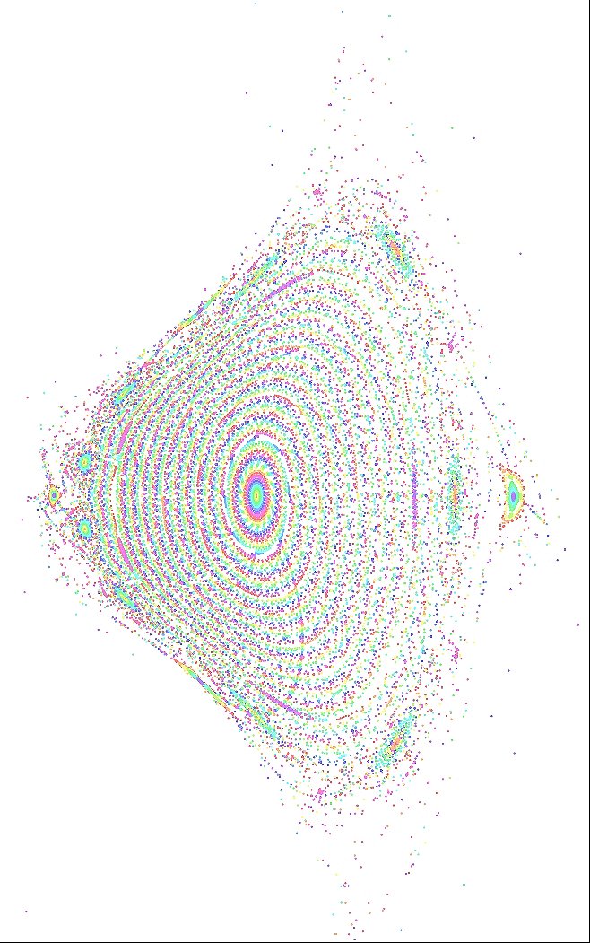
Fig 5 . 250 magnetic surfaces to observe small islands. The calculation-simulation lasted 394 seconds
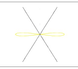
Fig. 1 . Magnetic axis in CNT for 64º and no drifts.
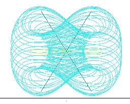
Fig. 2 . Near edge magnetic surface for 64º and no drifts for x+ = r = 170mm This figure is similar to Fig. 3 in [2]
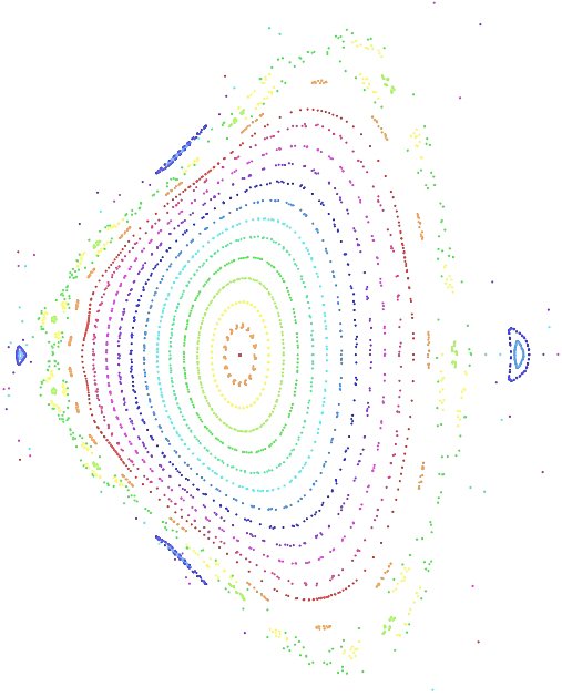
Fig 3 . Magnetic surface simulated with SimPIMF for the conditions angle IL/PF = 64º , I IL / I PF = 3.64 , Energy of electrons = 100eV , drifts ON .

Fig 4 . Superposition of the magnetic surfaces simulated with SimPIMF and from the CNT team . Both agree notable well so it further validates SimPIMF code.
.
Fig 5 . 250 magnetic surfaces to observe small islands. The calculation-simulation lasted 394 seconds
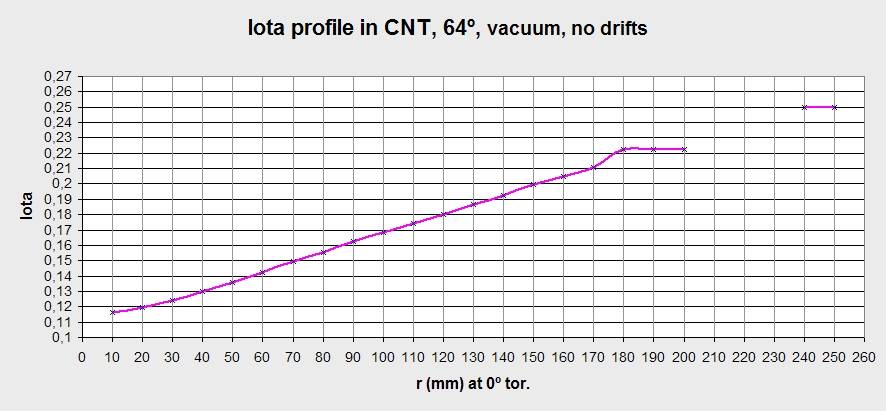
Fig. 6 . Iota profile on x axis (phi = 0 , romboedric surface). The opposite radial side is similar and has been removed. The flat areas correspond to the islands. [Expand to see the next comment]. The external island is related to rational 1/4 = 0.25, the previous 2/9 = 0.2222... , the gap without data are particles that escape during the simulation so the last closed magnetic surface is around x+ = 175mm, before the rational 2/9.
Date of publication 16-12-2006