Abstract : Description of the process to start up the AMETEK Dycor mass spectrometer, some information about the spectrometer and the first spectrum obtained.
The spectrometer
A second hand mass spectrometer was bought months ago but it was not installed due to lack of time. Now it has been installed, commissioned, and basic theory and practice of spectrometry has been studied.
The spectrometer is an AMETEK Dycor Quadlink quadrupole mass spectrometer (RGA) from ebay. It cost only 90€ plus a shipping and customs extra of about 200€. The cost of this unit new was more than 6000€ time ago.
It is a 1996 model equipped with an advanced power supply controlled by PC through RS-232 and a head with Electron Multiplier. The model has been replaced recently by the AMETEK Dymaxion model which is almost the same except for the electronics that now is a smaller compact box.
The spectrometer is composed by a power supply, an Electrometer and a head. Photos 1 y 2.
The Multiplier obtains about 100 times more sensitivity than a Faraday Cap. The Faraday Cap is the standard low performance sensor.
Installation
The Repeller at the tip of the head is about 30mm diam. while the internal diameter of the tubes in the NW40 flanges is about 33mm and moreover the flange of the head is a tyep CF. While an adequate coupler is ordered and received the head has been connected to a NW40 flange through a highly loaded o-ring from the NW40 rings. The Varian valve, previously used for the vacuum system, has a NW-40 flange with about 37mm internal diameter, which is enough for the Repeller diameter
Besides it was discovered later that the Multiplier should not be used in vacuum systems having oil pumps if a good quality oil filter is not installed. So the valve will be always closed except in some experiments (at the moment the difussion pump cannot be upgraded to a turbomolecular pump)
The spectrometer is installed near the Inverted Magnetron gauge and the TC gauge.
A code from Peter Horvath [1] was tried but up to now it has been impossible to receive data from the RS-232. The Quadlink receive data from the PC but the PC cannot receive data due to some unknown problem. So a standard RS-232 line input application is used at present.
First tries
The manuals were carefully read and the communications tested. The communications worked fine. The manuals for this AMETEK spectrometer are quite short and they lack of some important information. The help of the manua for CIS spectrometers from 'STANFORD RESEARCH SYSTEMS' much more detailed have been used to understand some details. Other information about the internal elements of the head, the function and the applied voltages are studied.
Because the spectrometer was likely to be broken (it is common to upgrade the instruments when a minor failure has appeared) and it is my first experience with an spectromenter, usually it is not clear if the spectrometer is damaged it is being wrongly operated.
The spectrometer did not worked at the first try.
One strange issue was a cut electronic line on the Electrometer, and another an error sign of 'Filament Open'.
By chance it was discovered that the 'Filament Open' error was caused by an interference of the electronic vacuum valve into the head or the electrometer.
The Electrometer was opened, the chips analysed, the lines followed and it was discovered that the Electron Multiplier HV line is connected to the Repeller pin (perhaps because this head has only 8 pins in contrast to the Dymaxion head that has 10, 2 specifically for the Multiplier). The RF pins, not indicated in the figure in the manual, were found.
The heart of the electrometer is a high quality AD515 OPAM (Monolithic Precision, Low PowerFET-Input OPAM) and a LF356 second phase of amplification. Very probably the electrometer works in varactor-bridge amplifier mode.
Later the cut of the electronic line became intelligible. Very possible the Multiplier power supply is replacing the standard Repeller power supply and internally the head might be modified due to lack of pins.
Moreover the Quadlink instructions are modified in an unlogic manner for a head with Multiplier Additionally it is not explained in the manual. Finally the logic of the unlogic Quadlink code was grasped. The Multiplier HV voltage is modified indirectly by the Repeller voltage instruction but it does not appear in the Repeller status but in the Multiplier status.
More and more multimeters were installed to know the real working voltages and currents and the logic of the Quadlink code when tested. Figure 3 shows many multimeters during the tests.
The first spectrum
The last voltage to test was the FOCUS voltage. Strangely it seems fixed to -13.8 and does not respond to the input data. In any case -20 is the standard so it is not a major issue.
The Multiplier voltage was raised to -350V (before it was set to low voltage due to the confusion Repeller-Multiplier HV) and some signals were promising. Later to -750V and results were obtained. The result is shown in Fig. 4 and Fig. 5. The scale logarithmic or linear is adequate depending of the analysis to carry out.
In this measurement the parameters are : Scan from mass 1 to mass 32 , 4 points per mass in Analog Mode, 500dwell time. The values are chosen to have a long time of scan anf few values.
For UST_1 stellarator, from mass 1 to mass 50, 8 points per mass in Analog Mode, 120 dwell time will be tried.
3 or 4 mass values centred in the peak for the gas used in the Leak Test (Helium or Argon or ...) will be enough for the tests.
Interpretation of the spectrum
Spectroscopy is a very complex discipline. However RGA for elementary or simple molecular gases is much more affordable.
Following the explanations in [2], the peaks observed in Fig. 5 corresponds to the species shown in Fig 6,
Fig 6 . Mass Spectrum (Logarithmic scale) of the residual gases in the UST_1 stellarator on 24-05-07. The main species and isotopes are indicated. Some data noise is observed perhaps because the metallic cap of the electrometer box was opened to connect the multimeters. Maybe they are impurities. In any case it is the first spectrum and it will be improved.
The species obesrved very possible are the next :
Mass : Species
1 H+
2 H2+
12 C+
14 N+
16 O+
17 HO+
18 H2O+
19 It is not clear. It could be 18O in HO+ or 17O in H2O+. The abundance of 18O is 0.2% and 17O is 0.04%
20 Isotope 18O in H2O+
28 Molecular nitrogen ion N2+
32 Molecular oxygen ion O2+
Further development
The electrometer will be closed. Leak test for the external ports will be carried out, perhaps under the plaster in a future. The spectrometer will help in the improvement of the vacuum quality because only one element (H or He or Ar) is convenient and now it can be checked.
References
[1] http://www.kfki.hu/~phorvath/ Code to control one model of Dycor Spectrometer (not exactly Quadlink)
[2] "Vacuum Diagnosis with an RGA" , www.thinkSRS.com
Fig 5 . Mass Spectrum (Linear scale) of the residual gases in the UST_1 stellartaor on 24-05-07. See the text for more explantions
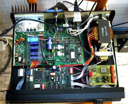
Photo 1 . Power supply and controls of the Dycor Quadlink Mass Spectrometer. Internal circuits.
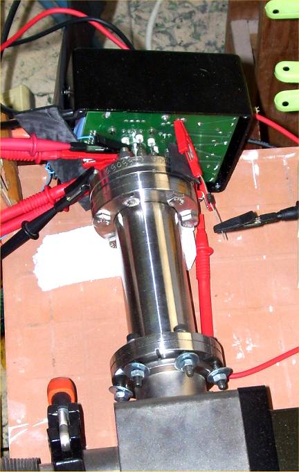
Photo 2 . Head (stainless steel cylinder) and Electrometer (in black + electronics).
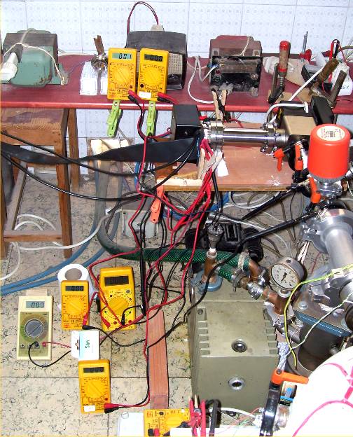
Photo. 3 . Test of the quadrupole head.
Fig 4 . Mass Spectrum (Logarithmic scale) of the residual gases in the UST_1 stellarator on 24-05-07. See the text for more explanations
Fig 5 . Mass Spectrum (Linear scale) of the residual gases in the UST_1 stellartaor on 24-05-07. See the text for more explantions
.
Date of publication 24-05-2007