Abstract : Details about the conditions and gradual improvements of pulses from #211. This pulse is the starting point of the experiments to achieve a satisfactory plasma for the size and possibilities of UST_1.
List of pulses and main parameters
The next are the first pulses after the installation of part of the ECRH system. See [1] for more information about the heating system in UST_1.
NOTE : The criteria to properly have a plasma [2] is not considered in the next. A notable plasma should be obtained at the end of the pulses so now the focus is the improvement of the systems and not the characterisation of poor plasmas or non-plasmas.
Meaning of columns:
# = number of order of the pulse
t = pulse length in seconds
B= approximate value of the magnetic field at axis
It = kAmpere-turns in each coil
P = Pressure in the vacuum vessel in milli-Pascals at the begining of the pulse
Pp = Pressure in the vacuum vessel in milli-Pascals during the plasma life.
W = Injected power = Forward -Reversed power from the directional coupler.
Wr = Reflected power
Contractions:
Simul = The pulse was simulated later to compare with experimental data.
| # | Date | t | B | It | P | Pp | W | Wr | Result |
| s | mT | kA-turn | mPa | mPa | |||||
| 226 | 7-2 | 2 | ~42 | 2.2 | 4 | 9 | ? | Nothing | |
| 225 | 7-2 | 2 | ~42 | 2.2 | 4 | 7 | ? | Nothing | |
| 224 | 7-2 | 2 | ~42 | 2.2 | 4 | 20 | ~80 | Plasma ok at ~2e18 m-3 | |
| 223 | 7-2 | 2 | 42 | 2.2 | 6 | 30 | ~80 | Plasma ok at ~2e18 m-3 | |
| - | |||||||||
| 222 | 24-1 | 2 | ~43 | 2.2 | 60 | - | First PLASMA | ||
| - | |||||||||
| 221 | 19-1 | 2 | ~43 | 2.2 | 22 | - | Nothing. Connector leak | ||
| 220 | 19-1 | 2 | ~43 | 2.2 | 22 | - | Test no TF's | ||
| 219 | 19-1 | 2 | ~43 | 2.2 | 29 | - | Plasma | ||
| - | |||||||||
| 217-218 | 17-1 | 2 | 42.5 | 2.16 | 40 | 26k | Nothing | ||
| 216 | 17-1 | 2 | 42.5 | 2.16 | 29 | 6k | Plasma | ||
| 215 | 17-1 | 2 | 43.4 | 2.2 | 54 | ? | Nothing | ||
| 214 | 17-1 | 2 | 42.5 | 2.16 | - | - | To know B | ||
| - | |||||||||
| 211-212 | 16-1 | 2 | - | - | - | - | A small glow discharge | ||
Results and improvements
Pulses #224 to #226
Conditions of the experiences:
* HN connector is installed on the VV. It is hermetic but a layer of glue faces the vacuum. It can outgass during the pulse.
* The dual directional coupler is installed and one diode detector is also installed at the forward port.
* The cable from the directional coupler to the HN connector plug is RG-214. RG-9 from waveguide to coax. adapter to the directional coupler. Both are about 20cm long.
* The sampling rate is set to 50 samples/sec. Only the AIMS pressure is recorded. The signal from the detector was tested but finally not recorded. Sampling is synchronised with the camera frames up to 0.01 seconds of precision. 30 frames/sec 640 x 480 pixels.
* A robust antenna of type L and a copper coaxial line of 20mm int. diam. is installed along the port. A piece of mica at the vacuum side to protect the HN connector.
* A spreadsheet is created to easily represent the results. Prepared for up to 8 inputs and 8 actions-outputs. Graphs are generated to analyse the results.
* The TF coils are on while the microwave is starting in order to record the first plasma at low pressure (the outgassing is still starting). The chronogram of the pulses is : TF coils ON from 3.0s to 5.0s. Microwave ON from 1.0s to 7.0s. Light bulb for synchronism and initial record of the antenna-limiter position and correction, ON from 0 to 9 and from 7.0 to 7.5 seconds.
Results :
- Cables and connectors withstand the RF power.
- Pulse #223 :
- A plasma is created. 3 phases can be distinguished : a faint start at 1 x 10¹⁸ m-3, an instable toroidal plasma for a second at ~3 x 10¹⁸ m-3 and a very powerful flash during 0.5s due to excessive pressure and/or RF power at ~5 x 10¹⁸ m-3 .
- The best plasma appears at a neutral density from 1.5 to 2.5 x 10¹⁸ m-3. It also happens in the pulse #224 so it is a starting point for future pulses.
- The relation between the outgassing and the instant and the magnitude of the plasma is clearly observed.
- Outgassing-leaks are much lower than in previous pulses. The outgassing in the pulses #225 and #226 is even lower. However a plasma is not created in these pulses.
- The plasma disappears exactly 0.1 seconds after the TF signal OFF. The real OFF of the plasma might be delayed 0.1s due to the delay of the series of 3 switches for the TF power.
- Pulse #224 :
- The plasma lasts only some tenths of a second. Not known the reason.
- The best plasma appears at neutral density from 1.5 to 2.5 x 10¹⁸ m-3. It also happens in the pulse #223 so it is a starting point for future pulses.
- The magnitude of the plasma (a small light in the antenna or a medium plasma or a flash) is clearly related to the outgassing. Even some rough estimation of the relation is possible.
- The pressure increases only ~0.002Pa after a small marginal plasma of about 0.1 seconds. However ~0.01Pa after a flash plasma of about 0.1 seconds.
- Pulse #225 and #226 :
- Only small marginal plasma inside the antenna is observed at some moments. No toroidal plasma is created. Pressure reaches only 7 and 10 Pa during the TF ON period. It is a positive behaviour (less outgassing after some cleaning plasmas). If gas is injected perhaps a better plasma would be generated.
Necessary improvements :
* The two diode detectors are totally necessary to know the injected power that creates a good plasma. It seems (from a rough degree of an interference) that half of the max power creates a better toroidal plasma than full power, about 100W.
* The interference (or other phenomenon) on the AIMS gauge signal need to be reduced.
* A precision gas valve to inject small amounts (leak style) Argon, Helium or H is necessary to try to obtain a neutral pressure around 2.0 x 10¹⁸ m-3 . Perhaps it will be possible after some cleaning plasma or glow discharges.
* The A/D card should be improved. More inputs installed.
* Grounds improved to decrease interferences.
Pulse #222
Conditions of the experiences:
* The images and the pressure from the inverted magnetron are synchronised up to 0.1s accuracy.
* Sampling frequency of pressure set to 50Hz
* The type N connector is protected by a mica layer. The plastic support in the male plug is removed. Plastic elements are minimised.
* Antenna of type L, far from the plasma centre, is installed. It is calculated by expressions from "Calculo de antenas" [3]
Results :
- Pulse #222 : 24-01-2007. First plasma, but still a low quality plasma. The period of higher quality lasts 0.7 seconds and after that it almost disappeared perhaps due to excessive outgassing or connector leak. However the plasma is very unstable at any time. TF coils are ON (Bo=~43mT , 2nd harmonic at 2.45GHz) while the plasma is or seems toroidal (difficult to assure because of the perspective of the camera).
- The Type N connector started to leak during the pulse.
- Pressure raised from ~0.06Pa to 1Pa in 0.5 seconds (P from inverted magnetron, 1Pa~1x10²⁰m-3), more later but the TC is too slow to synchronise measurements.
Necessary improvements :
* HN hermetic connectors need to be installed. Or a serious vacuum ceramic connector.
* Extract the antenna 5mm and add a better ground behind the antenna.
* RF measurement will be
installed and plasma basic diagnostics planned.
Pulses #219 and #221
Conditions of the experiences:
* The diffusion pump is working.
* 6 batteries.
* Some pressure information is recorded.
Results :
- Pulse #219 : A plasma similar to the one in pulse #218 is produced. It lasted 1 second. However the pressure also raised excessively.
- Pulse #220 : Pulse without TF current in order to discover if the increase of pressure is caused by the walls of the VV or from the antenna. No plasma appeared but the pressure raised. However a low T gas cloud could exist or the Type N connector produce outgassing.
- Pulse #221 : The Type N connector definitively breakdown and a large leak appeared.
- The VV was opened after the pulse #221. The type N internal part of the the type N connector burnt. Very possible the outgassing come from this point.
Necessary improvements :
* A new RF vacuum feedthrough of good quality is totally necessary. The old idea of Type HN connector might be the best. Hositrad and other companies supply type N and HN vacuum feedthroughs but are expensive, ~600€ for a high frequency flange-connector.
HN bulkhead connectors have just been ordered.
A provisional solution while the new connectors arrive might be the elimination of the internal connector to allow the first outgassing to escape in order to avoid the initial increase of pressure that might trigger the discharge (arc, glow).
* Synchronise the image recording, pressure recording and pulse sequence.
Pulses #213 and #218
Conditions of the experiences:
* The diffusion pump is working.
* 6 batteries.
* About 100W of RF at 2.45GHz is injected. The measuring devices for RF heating have been ordered but not yet received.
* The antenna is thought to be also a limiter. It is totally inside the possible plasma.
Results :
- Pulse #215 : TF coils started 2 seconds after the microwave was on. It was considered too short and the next pulse is larger.
- Pulses #216-218 : The chronogram of the pulses is : TF coils ON from 4.5s to 6.5s. Microwave ON from 1.0s to 7.0s. Light bulb for synchronism and initial record of the antenna-limiter position and correction, ON from 0 to 9 and from 7.0 to 7.5 seconds.
- Pulse #216 : A plasma, or almost, has been created. The plasma lasted only 0.5 seconds. Vacuum was 40mPa before the pulse started. At some moment during the pulse the pressure increased abruptly (the A/D converter was not connected to the gauges so the values and time is only roughly known from the multimetres). 6 Pa (9 x 10²⁰ m-3 at 25ºC) are measured at the end of the pulse (even after some possible time of vacuum recovery). The brass antenna is inside the plasma region, near the centre of the plasma so this phenomenon was expected. But it was thought that the antenna could act as a limiter. Perhaps part of the impurities, the contamination, comes from the walls of the vacuum vessel and part from the antenna. In any case, the next step is to create a more definitive antenna.
Two alternatives are planned : 1) A "L" antenna in order to shorten the length of the monopole to give space for the plasma or 2) a dipole antenna.
The dipole antenna should be a folding antenna to allow the introduction through the port.
Any type of ICRH style antenna is not planned.
An L antenna might be the first improvement because it is simple.
A straight stub antenna can be installed at the bottom of the vessel but a curved short coaxial line is necessary to feed the antenna.
- Pulse #217 and #218: No plasma is observed. Perhaps the camera has too low sensitivity or perhaps the provisional connection of the waveguide in the microwave has failed. The pressure increased up to 26Pa (this value was clearly measured in pulse #217). It is strange because a plasma is not observed and the pressure increased. The plastic feedtrhough of the Type N connector must be taken into consideration. It is the first time that a plastic piece is used inside the VV of UST_1. Perhaps RF heat and outgassing.
Necessary improvements :
* The new antenna will be built.
* Connect the vacuum gauges to the A/D converters.
* Improve the waveguide connection.
* Look for a commercial feedthrough
Pulses #211 and #212
Conditions of the experiences:
* It is a test. Only the rough pump is ON so presure is high, around 13 Pa.
* 5 batteries form the power supplies.
Results :
- Pulse #210 : Nothing.
- Pulse #211 : A small 'plasma' inside the coaxial line. The pressure is the lower possible for glow discharges. In any case the pressure is high so it lacks of relevance for fusion.
References
[1] "ECRH system in
UST_1 and first tests" ,
Vicente M. Queral. See List of
all R&D
[2] "Introduction to plasma physics and controlled fusion", F. F. Chen , Plenum Press, Second Edition. , pg 12 .
[3] "Calculo de antenas" Armando García Dominguez. Marcombo Boixareu editores.
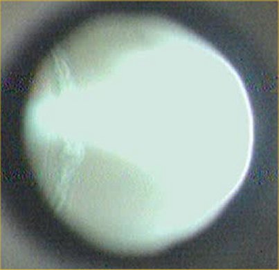
Photo 2 . Pulse #222. 24-01-2007 . First plasma but still a low quality plasma. The period of higher quality lasts 0.7 seconds. The plasma is very unstable at any time and the outgassing during the plasma (from connector, antenna or walls) is excesive. The plasma seems toroidal but it is difficult to assure because of the perspective of the camera.
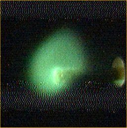
Photo 1 . Pulse #216. 17-01-2007 . First 'plasma'. Perhaps it is not properly a plasma but it will be improved soon. Another weak 'plasma' is observed inside the coaxial line. The plasma lasted only 0.5 seconds.
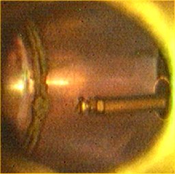
Photo 2 . Pulse #216. First antenna. It is a stub antenna 1/4 wavelength . The right side is the end of the coaxial line, near the port.
Date of publication 17-01-2007. Continuous updating