Abstract : The calculation of the thermal loads in one particular resistive conductor used in high field magnets and fusion research is described. As one example the copper hollow conductor of the OVF coil of the CTH torsatron [1] at Auburn University is taken. Additionally the process of calculation using GMSH and ASTER is briefly described. ASTER is a code developed by EDF (Electricité de France) under GNU licence and GMSH is a pre and post processor usually used with ASTER . The objective is to test different methods of cooling and set-up Code_ASTER for thermal calculations.
General description
The analytical calculation of the thermal
evolution of the OVF hollow conductor is compared with
the results from Code_ASTER.
The OVF coil in CTH [3] is formed by a 1.4cm side squared conductor of copper with a hole of 0.635cm diameter and 126.7m long. 16 turn form the winding
Both calculations start from the knowledge of the heat-transfer coefficient h . This value is calculated using the method in Montgomery [2] and the common and more general expressions that appear in many books of heat transfer [4]
The factors and hypothesis taken into account are : turbulent flow inside a pipe, a sudden contraction of the flow at the entrance region of the conductor, totally smooth tube, the effect of the change of properties from the hot surface to the bulk temperature, properties of the copper and water calculated at each working temperature. A Petukhov enhanced expression is used for h.
Other input data is :
T cooling water at the inlet = 20 ºC
T on the surface of the tube at the middle point= 42ºC (result of iteration)
Speed of the flow = 5.91 m/s
Length of each individual tube = 7.92m = total length /16 , so to avoid excessive rise in T at outlet.
T bulk of the water at the middle point of the tube = 37 ºC (result of iterations)
The source of heat Ws = 1.907 * 107 W/m3 at 42ºC and I = 5240A. Ws refers only to the conducting section while in Montgomery Wv refers to the total average power in the winding.
The result after a few iterations was h = 29770 W/m2 K . Using the far simpler expression in Montgomery [2] the result is h = 25000 W/m2 K . The higher value is mainly due to the influence of the entrance effect and the change of viscosity from the wall to the bulk water.
Meshing with GMSH
GMSH is a package distributed under the terms of the GNU General Public License (GPL). It is an automatic 3D finite element grid generator with a build-in CAD engine and post-processor. It is one of the two more common meshers used with ASTER . It can be download and is documented in http://www.geuz.org/gmsh
A planar modellisation of the section of the conductor is shown in Graph 1 . 487 nodes and 974 triangular elements were generated using GMSH pre and postprocessor.
Solution using ASTER
Analytically is clearly seen that the increase of the temperature in the copper is low, less than 1 K . However the calculation is carried out to test the Code_ASTER in thermal calculations.
The documentation for Code_ASTER is at http://www.code-aster.org . ASTER is a code developed by EDF (Electricité de France) and other organizations under GNU licence. In one analysis in the ASTER web page the quality of this package is regarded as similar or even superior to ABACUS, a well known FEA package.
The input data are the properties of the copper, the heat-transfer coefficient of water-wall given above (h = 29770 W/m2) , the source of heat per unit of volume and the bulk temperature of the water (taken 20ºC , at the entrance).. The source of heat is significantly dependant on the temperature of the copper which depends on the whole thermal problem. Although ASTER admits the use of functions as input data, here a constant average value of the resistivity is supposed.
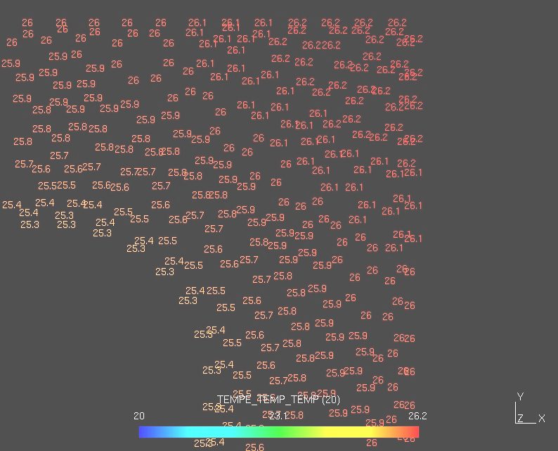
The numerical results for a quasi-stationary state, at t=10sec, are shown in Graph 2. The increase of temperature form wall to bulk water is IncT = 5.3 K . The maximum increase of T in the conductor is IncTC = 0.9 K and the minimum 0.7K.
The analytical solution gives IncT = 5.28 K.
The reasults for IncT agree exactly.
A transitory state at t=2 is shown in Graph 3 .
The increase of Twater from inlet to outlet is 32 K under these conditions
Postprocesing
All graphs were obtained using GMSH.
Further developments
A more accurate solution using variable parameters should be convenient to reach the maximum precision and to further test the Code_ASTER.
References
[1] "MHD stability studies of current-carrying plasmas in the compact toroidal hybrid". S. F. Knowlton, G. J. Hartwell, C. Watts, J. D. Hanson Department of Physics, Auburn University.
[2] "Solenoid Magnet Design", D. Bruce Montgomery, 1980, Robert E. Krieger Publishing Company.
[3] Personal Information from Hartwell, G.J. , Auburn University
[4] "Heat transfer" Schaum's outlines. McGraw-Hill
"Transferencia de calor técnica" B. Sigalés. Ed. Reverté
![]()
Graph 3 . Map of temperatures in a transitory isntant , t=2sec

Graph 1 . View of the modelled section
Graph 2 . Numerical result of a quasi-stationary simulation
![]()
Graph 3 . Map of temperatures in a transitory isntant , t=2sec
Last Update 30-05-2005