Abstract : Following the testing of the MEMCEI v2.1 code, the re-calculation of the stray field in HT-7U tokamak is carried out. PF coils are modelled and PF currents from documentation are taken as example. The results are compared with the correct results from the HT-7U reports.
Modellization
The system is modelled following the data in Table 1 in [2]. These data have been checked with the Fig2 in [1] and the position of the PF coils has only minor discrepancies. Another model which can be seen in page 5 of [3] seems to be more modern than the used here although the differences are mainly at PF13. Finally it was decided to use the older model because more information is available about it.
Another different preliminary design of the PF coils for the HT-7U was found but it has not been used here.
Only one loop of current for each PF is used as a first approximation. Each loop is formed by 49 finite elements. It could be enough precision because of the notable accuracy of the MEMCEI v2.1 code, at least outside the conductors.
Z axis is the vertical center of the tokamak, Y axis contains two simetrical TF coils.
Magnetic Field
The currents used for the modellization come from Table 1 of [2] Plasma current is 0 A. TF coils are loaded with 14307A , the nominal current for Bt=3.5T .
In the Graph 1 we can see the stray field at the equatorial plane in the plane of a TF coil ( Y+ axis) calculated using MEMCEI. The values at points expressed in Table 2 of [2] are copied in column HT-7U [2]
| R ( m ) | Bz ( T ) : MEMCEI | Bz ( T ) : HT-7U [2] |
| 1.38 | -0.00089 | -0.00118 |
| 1.7 | 0.00053 | .0004 |
| 1.78 | 0.00064 | .00053 |
| 1.942 | 0.55 | .00045 |
| 2.550 | -0.0027 | -0.00291 |
At a first sight the deviation seems high, however it is only at the 10-4 T level as we can see with the higher precision at R=2.55 m. Considering some indetermination of the model and that only one loop per PF coil is used the approximation can be enough. Additionally the magnetic field ranges from about 4 T inside the PF1-PF3 to 4 10-4 T at the plasma centre, so making more difficult the precision.
The MEMCEI results for the module of the By and Bz components of the magnetic field can be seen in Graph 2. The correct results calculated in [2] are expressed in Graph 3.
The results match reasonably well although the 0.002 T line and others have a different trajectory at the end. No analytical values are available at this moment to compare the results numerically.
Further developments
Another model with more elements for the PF coils would be necessary and to revise the original exact geometry of the model used in [2].
[1] “Engineering of the HT-7U Superconducting Magnet Systems”, S.T. Wu, W.Y. Wu, et al, Institute of Plasma Physics, Chinese. A of. S.
[2] "Design of the Poloidal Field System and Plasma Equilibrium of HT-7U Tokamak" , Wu Weiyue and Li Baozeng, et al. , Institute of Plasma Physics, Chinese Academy of Sciences.
[3] "The Engineering Design of
the Poloidal
Field System of HT-7U Tokamak" . Wu Weiyue, Li Baozeng, Cao
Yunluo. Presentation found as wwy-6.pdf on the internet.
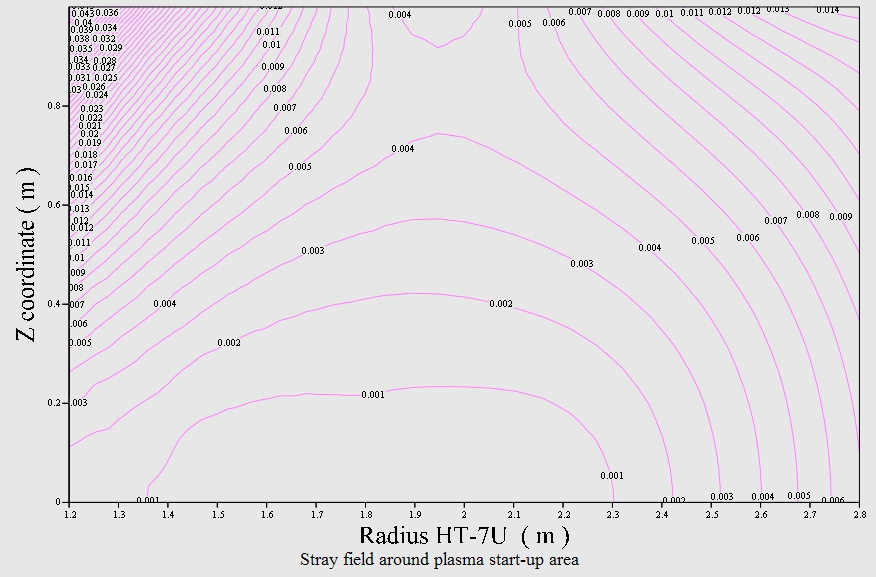
Stray field at the area of the plasma centre. Calculated using MEMCEI.
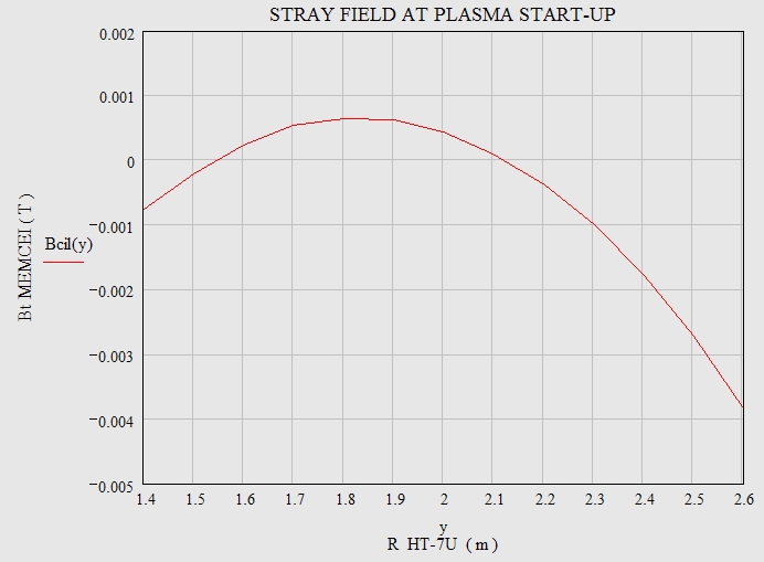
Graph 1 . Stray field at the equatorial plane in the plane of a TF coil ( Y+ axis)
Graph 2 , Stray field at the area of the plasma centre. Calculated using MEMCEI.
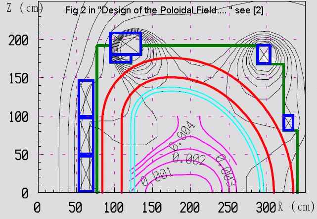
Graph 3 , Stray field at the area of the plasma centre as shown in Fig 2 of [2]
Last Update 11-02-2005