This version is an evolution of the first code, MEMCEI v1.0. This version uses a cylindrical element as the modellization element instead of a spherical one. The experience described below encourage me to continue testing this version as a possible satisfactory alternative.
The version v1.0 of the MEMCEI code needed a substantial number of elements to achieve a notable precision in the results. See "Last results". In order to increase precision maintaining the CPU requirements a new version of the code has been developed.
The version v1.0 models the wire as a series of spheres whose radius is the radius of the modelled wire. Inside the sphere the magnetic field is proportional to the cross product of the element of wire and the position vector. Even if the length of each element of wire is small in comparison to the radius of the wire, there is a notable deviation in relation to EFFI code results. See "Last results" using 40000 elements.
Modellization
At a first sight, the modellization of the elements as small cylinders seemed to be a better method. So, a code using the expression
B outside
for each element of wire was used. This expression was transformed in a vectorial form. The finite element code v2.0 models each line of current by a modified Ampere-Laplace law. The modified law, as explained above, is applied outside and inside the theoretical wire.
The code was tested using a cuasi-infinite straight conductor and compared with the exact expression for an infinite round conductor, both inside and outside of the conductor. The resultant magnetic field was the same inside the condutor and similar outside (less similar when further from the conductor supposedly due to the non-infinite modelled conductor). The recalculation of HT-7U was carried out as a further test for this code, named MEMCEI v2.0.
Magnetic Field
The MEMCEI code v2.0 has been compared with the TF coils of the HT-7U tokamak, one of the most recent superconductor tokamaks. The TF magnetic field of this tokamak was calculated by the HT-7U team using the EFFI code. The same code was used in Wendelstein 7-X.
Data corresponding to the HT-7U geometrical inputs and results come from [1] [2] and [3]. The model in HT-7U is divided into 164 current elements, the current is 14,3077 kA to obtain 3.5 T at the plasma centre, having 130 turns each TF coil. The torus is composed of 16 TF coils.
In this calculation using MEMCEI v2.0 800 elements of current are calculated, distributed in 16 TF coils and using only loop of current per coil. This amounts up to 50 current elements each D shape loop. The results obtained using the most accurate HT-7U geometry available till now are expressed in graph 1.
The discrepancy between this calculation and the EFFI-HT-7U team calculations is less in this case (v2.0) than in v1.0 using more than ten times less elements. This point to a importantly improved code. Calculations with more elements will be done so to try to reach more accurate results or, in case, modify the code.
More accurate knowledge about the modellization of the currents in the EFFI-HT-7U model is necessary to compare the toroidal magnetic field inside the conductors.
Forces
Presently the forces in this case has not been calculated yet (see "Last results" for an approximation)
An interface between the magnetic field calculations and mechanical stress using the French Code_Aster is planned to be developed so to calculate in same kind of evolutionary way the whole system including magnetic, electrical and mechanical specifications.
[1] “Engineering of the HT-7U Superconducting Magnet Systems”, S.T. Wu, et al, Institute of Plasma Physics, Chinese Academy of Sciences.
[2] “The Analysis and Calculation for the Toroidal Magnetic field of HT-7U”, Chen Wenge, et al, Institute of Plasma Physics, C. A. S.
[3] “Design of the HT-7U Tokamak Device”, S.T. Wu, et al, Institute of Plasma Physics, C. A. S.
B inside a long round condcutor
Diagram for B outside a straigh conductor
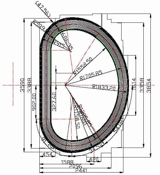
View of the TF coil HT-7U
as shown in [2]
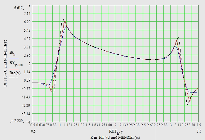
Graph 1 : HT-7U Bt calculations using EFFI and MEMCEI codes.
- Bth is the magnetic field in the toroial axis using EFFI,
- BYy100 is the toroidal magnetic field at the Y axis using MEMCEI v2.0 (800 elemets)
-Bto(y) is the toroidal magnetic field at Y axis using MEMCEI v1.0 (9600 elements)
- RHTh is the radius of the HT-7U tokamak, data from graph in [2]
- y is the radius of HT-7U for MEMCEI
Last Update 04-02-2005