Abstract : The calculation of the displacements and stress in the metallic case of the TF superconductor coil in HT-7U is described. It is used the input data from MEMCEI v2.1 and from some reports of the HT-7U team. Additionally the process of calculation using GMSH and ASTER is briefly described. ASTER is a code developed by EDF (Electricité de France) under GNU licence and GMSH is a pre and post processor usually used with ASTER . The objective is to setup and test the Code_ASTER and other related tools applied in fusion engineering calculations.
Modelling
The geometry of the TF coil follows the Fig 2 in [1]. Some values that are not numerically expressed are graphically obtained.
In this calculation only the case is modelled whereas in [1] and [2] the superconductor winding pack is also modelled. So the results might be slightly higher both in deformation and stress.
The hollow case having D shape is defined as 50 hollow polygonal volumes. On each volume one of the 50 forces calculated by MEMCEI is applied.
Meshing with GMSH
GMSH is a package distributed under the terms of the GNU General Public License (GPL). It is an automatic 3D finite element grid generator with a build-in CAD engine and post-processor. It is one of the two more common meshers used with ASTER which implements a build-in importing command. It can be download and is documented in http://www.geuz.org/gmsh .
In this first calculation using GMSH, 5317 nodes and 15775 tetrahedrical elements were generated.
Solution using ASTER
The documentation for Code_ASTER is at http://www.code-aster.org . ASTER is a code developed by EDF (Electricité de France) and other organizations under GNU licence. In one analysis at ASTER web page the quality of this package is regarded as similar or even superior to ABACUS, a well known FEA package.
The present model is solved using "3D modellisation" and the constraints are supposed to be DX=0.0, DY=0.0, DZ=0.0 at the edges of the straight portion of the TF coil.
Only FX forces are weightily applied on two vertices of each one of the 50 polygonal volumes. Gravity is not considered. The forces are calculated in [3] and displayed in Graph A.
The properties of the steel are: Young’s modulus 204GPa ; Poisson’s ratio 0.3 corresponding approximately to steel 316LN at 4K.
All this values were defined using EFICAS, a tool to easily define the FEA model in ASTER.
The differences between this model and the data expressed in [2] are important but it will improved when more information were available and more ability in the use of the Code_ASTER and GMSH were acquired.
The deformed shape calculated by ASTER using the above conditions and data is shown in Graph 1 . The maximum deformation is about 0.0114 m = 1.14cm. This value is slightly higher than the 1.027cm calculated in [2] , Table 3.5 . However, in the ASTER calculation the interior superconductor is not modelled.
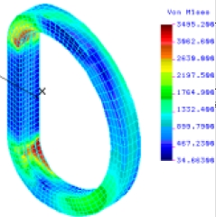
Since the FY forces are not introduced in this model, the total Von Mises stress might be inferior to the result in [2]. However the result is no previsible due to the inexistence of superconductor core.
The distribution of Von Mises stress calculated by ASTER using the above conditions and data is displayed in Graph 2 . The maximum value is 4.75 x 10⁸ Pa = 4842 Kgf/cm2 .
The Von Mises distribution calculated in [2], see Graph 4, cannot be compared with Graph 2 because in this calculation there is no component Y of the forces, the centering force. As a result the distribution in Graph 2 is symmetrical but not in Graph 4.
Postprocesing
Graph 1 and 2 was obtained using GMSH.
Further developments
The next steps should finish the model with the introduction of the superconductor, use the exact values of Young’s modulus and Poisson’s ratio and add the effect of the component Y of the forces. A new comparison with the report [2] is needed.
References
[1] "The Analysis and Calculation for the Toroidal Magnetic field of HT-7U" , Chen wenge(陈文革), Pan yannian(潘引年), Wu songtao(武松涛), Weng peide(翁佩德). Institute of Plasma Physics, Chinese Academy of Sciences.
[2] "Toroidal magnetic field in normal operation" . Documentation about HT-7U found in : http://202.127.205.62/IAC/disk/
Design of the EAST(HT-7U)Project/2.2-2.pdf
[3] "Profile of the forces on TF coils of HT-7U. Comparison with the results of the HT-7U team" , Vicente M. Queral . See "Present Status" or “Last results”.
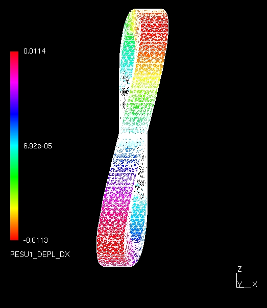
Graph 1 . Deformation of the TF coil under out-of-plane loads. Units in meters. Calculation using ASTER-GMSH
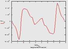
Graph A . Modellisation of the PF coils in HT-7U to be used it in MEMCEI. See [3] for more details.
Graph 1 . Deformation of the TF coil under out-of-plane loads. Units in meters. Calculation using ASTER-GMSH
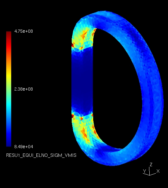
Graph 2 . Distribution of Von Mises stress. Units in Pa. Calculation using ASTER-GMSH
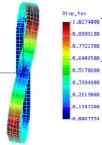
Graph 3 . Copy of the results from Table and figure 3.5 in [2]
Deformation of the TF coil under out-of-plane loads. Units in cm
Graph 4 . Copy of the results from Table and figure 3.5 in [2]
Distribution of Von Mises stress. Units in Kgf/cm2
Last Update 08-03-2005