Abstract : The main systems of the stellarator are improved. The ECRH system has been equipped with a Double Stub Tuner to try to match the RF to the plasma. The Data Acquisition System is being upgraded to receive the signals from the Dual Directional coupler (ECRH), the Langmuir probes and the TF current signal. The leak of oil in the mechanical vacuum pump has been repaired. The prospect of an optical spectrometer using the digital camera has been tested.
Repair of the mechanical pump
A relatively abundant oil leak appeared some time ago. The provisional solution was to extract the vacuum oil after each session of experiments.
Later some pages of the manual for the Pfeiffer DUO 0004A pump were obtained after long insistence (the central offices of Pfeiffer were kind and helpful but the Spanish representative was evasive) . Also the foreseeable pieces to repair the pump were bought time ago from 'Precision Plus', an efficient American company. Two shaft seals, support ring for the seals, gasket and some special springs were ordered and received.
The minuscule figures in the few pages of the manual were carefully observed, the pump was opened carefully, see Photo 1. Several tools to extract the clutch, the measuring coil and the shaft seal were manufactured. Photo 2 is a tool to extract the clutch. Photo 3 shows pieces and tools in relation to the shaft seal.
The shaft seal was extracted using an acetone solution that softened the rubber and allowed an easy extraction of the seal without scratching the hub.
All the pieces were reassembled and luckily the seal was not leaking at all.
Upgrading ECRH system. Matching impedances.
The system is described and calculated in [1] and some other publications cited in this reference.
A Double Stub Tuner Weinschel model DS109 was ordered from ebay and received. It has been installed on the RF line, previous to the Dual Directional Coupler. It is shown in Photo 4. Two outputs are observed, each one including an attenuator of 20dB and a Low-Barrier Schottky Diode Detector.
The reception of the signals from the PC has been tried. At present major interferences are received and the data is unusable. The interferences remain even after the achievement of good results for the TF current signal (see next chapter) and after some improvements in the grounding and shielding of the boards. It should be solved soon. A multimeter measures the signal correctly, without interferences.
Using the code online [2], from North Dakota State University, and trying for a range of possible Z loads (the plasma impedance is unknown) the results are:
The stubs are considered in points 1 and 3 so the distance is 0.335 times the wave length. 0.375 is recommended but it is impossible with the Weinschel DS109 for 2.45GHz.
Stub regulation
For most of the values of R load and X load the length L2B (web diagram) is around 56mm so the movement of the stub (the stub has an internal permanent depth of 26mm) will be 30mm as a first try. Values tested are the combination of Z = 2 , 5 , 15 Ohm +- 100 , 50 i Ohm . This values are in-between the foreseen impedance of the plasma. However this rough values come from a reference not very reliable.
Therefore only the stub A , L2A will be modified to try to increase the plasma performance. Later a fine adjustement could be carried out.
The manual for the Weinschel DS109 migth be received from the company in a next future.
Improving the data acquisition system
Some improvements are implemented :
- A good ground is connected to the A/D cards. It diminished the interferences, at least for the TF current signal.
- The TF current signal is connected to the A/D card. This signal is a voltage drop along one of the TF leads. It has been referenced to ground at the '-' pole of the batteries. The resolution and accuracy must be high because the interval of ECRH resonance is narrow. The experimental resolution, including interferences, is 0.3% (5 units out of 1500 units) but the accuracy need to be verified because it depends mainly on thermal drifts. Not more than 1% of error is expected. It is enough to know the magnetic field within an error of about 1%.
- A second A/D card has been installed and satisfactorily tested. See photo 5. It is prepared for the Langmuir probes and other new diagnostics. Now there are 8 differential inputs implemented by means of an instrumentation OPAM layout. The minimum signal can be in the range of 0 to 2mV.
- The two signals from the ECRH power coming from the Schottky Diodes Detectors were connected to the card nº1 (right) but in the Photo 5 they are removed. The interferences were excessive. The A/D cards and the analog interface (at the left, covered with aluminium sheet) were covered with aluminium sheet but the interferences seem to come from the ground~ECRH and not from the space.
- The signal from the AIMS vacuum gauge was set up long time ago.
Test of visible spectroscopy
The possibility of optical spectroscopy using digital cameras and a good quality optical prism spectroscope is tested and analysed.
In photo 6 the first test is observed. Perhaps a slight improvement in focus could be obtained. The spectrum of a compact fluorescent light bulb is taken with the standard digital camera in UST_1 and by means of a MEIJI TECHNO optical spectroscope between the light and the camera. It is a high quality hand held Japanese spectroscope.
However the resolution of the camera is 640 x 480 pixels in RGA mode and it is insufficient to resolve some lines. Moreover the sensitivity of the CCD for this camera is low as was discovered during the e-beam field mapping experiments and it will be poor for plasmas with low power on the visible spectrum.
It could be used as a first rough idea of the spectrum of the plasma. It will be checked in some next plasmas.
It needs an initial calibration that might be generated with special lamps whose spectral lines are known. For example the Philips spectral Cadmium lamp [3], Black light fluorescent lamps or similar.
Further developments
Avoid the interferences for the two ECRH signals.
Acknowledgement
I thank the 'Berstron Group' and their employees. They offered the A/D cards, power supplies, and information about the cards, the code to use the cards, about grounding and shielding techniques, etc.
References
[1] 'ECRH system in UST_1 and first tests' . Vicente M. Queral. See "List of all R&D"
[2] Double stub tuning
: http://www.ece.ndsu.nodak.edu/
%7Eronelson/mes/programs/dst.htm , North Dakota State
University
[3] 'The Double Amici Prism Hand-Held Spectroscope in Practice' , http://ioannis.virtualcomposer2000.com/spectroscope/amici.html , I.N. Galidakis
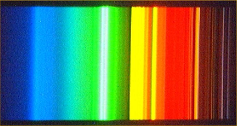
Photo 6 . Test of optical spectrometry. Here the spectrum of a compact fluorescent light bulb is taken with the standard digital camera in UST_1 and by means of a MEIJI TECHNO optical spectrometer between the light and the camera.
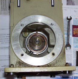
Photo 1 . Pump case without motor. The clutch and the measuring coil is observed at the centre.
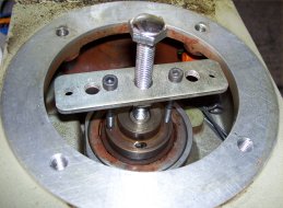
Photo 2 . Special tool to extract the clutch of the vacuum mechanical pump.
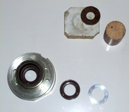
Photo 3 . (Top) Tools to introduce the shaft seal. (Bottom) Shaft seal (centre), support ring (right), hub (left).

Photo. 4 . Double stub tuner installed in the ECRH system.
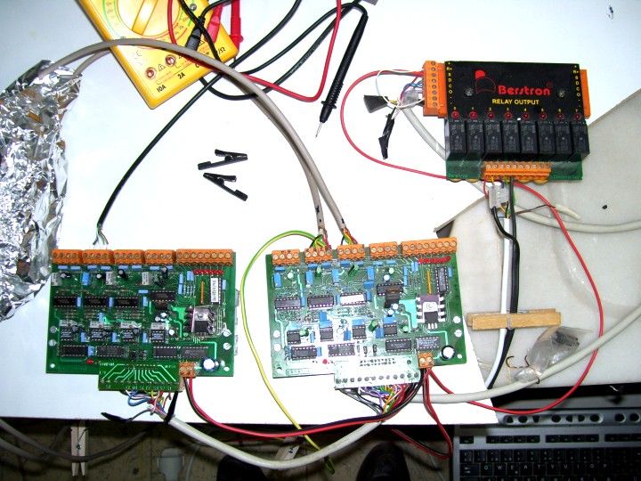
Photo 5 . Two A/D cards and output interface (right top). On the left, covered with aluminium sheet, analog interface between signals and A/D cards.
Photo 6 . Test of optical spectrometry. Here the spectrum of a compact fluorescent light bulb is taken with the standard digital camera in UST_1 and by means of a MEIJI TECHNO optical spectrometer between the light and the camera.
Date of publication 31-05-2007