Abstract : Photos and video of the experimental results of magnetic surfaces. Some simulations using SimPIMF are carried out to compare the experimental magnetic surfaces with the theoretical ones. Only some points of the surfaces appear due to poor vacuum. The e-gun was reduced and some improvements were done to finally obtain these apparently poor quality images, but very difficult to obtain in a small low cost stellarator. The consequences of the results are highly positive because they give further support to the correction of UST_1 design and construction.
Conclusions
- Magnetic surfaces are obtained and they agree with the theoretical simulations. Thus a notable degree of accuracy has been achieved in the construction of the stellarator. (The measured accuracy is better than 0.5% of the major radius for manufacturing + assembling)
- The toroidal device to mechanise grooves for modular coils was a satisfactory idea.
- The style of stellarator chosen among a wide variety was a feasible one. The selection of a modular, external wound coils, frame plaster made, circular-toroidal shaped stellarator among dozens of possibilities was not an easy choice.
- SimPIMF code has some degree of accuracy and correction, otherwise the experimental results would have not agreed with the simulations.
- The optimization of the magnetic confinement was useful and correct in some degree. Plasma size, Iota in the gap below 0.333 , enough shear, maximum magnetic well, low Bmin and magnetic ripple, and smooth magnetic surfaces was optimized using SimPIMF code. The long process of optimization would have been uselss if SimPIMF code had been notably incorrect.
- UST_1 is a stellarator and not only an artistic toroidal light bulb.
General description
The field line mapping system for UST_1 was design some time ago and it is described in [1]
In essence it consist of :
a) An in-site made electron gun of small size (20mm length and 6mm diameter for the new small model) formed by very low cost materials (about 3€).
b) An oscillating fluorescent rod of 1mm diameter that is driven by a removable external magnet. It oscillates freely during the pulse and the magnet is removed to a distant location during the pulse. The materials of this device costed ~0.3€.
SimPIMF, described in other pages, is used to compare the experimental results and the simulated predictions.
The whole list of pulses carried out is tabulated and briefly described in [2].
Other general explanations about the difficulties and solutions to record the magnetic surfaces are reported in [3].
In [2] only 3 points were recorded due to the excessive size of the e-gun and perhaps external magnetic perturbations.
In the present experiments a very small e-gun of only 6mm diameter is used. It allows the recording of some deeper magnetic surfaces without collision of the e-beam with the back of the e-gun, see Image 3. The power and quality was so poor using the 6mm e-gun that the points were weak and diffused. Some decisive improvements were done for the pulses #197 to #202 which are described next.
Photos 1 and 2 are the original frames from the camera record. A minor stretch of the image of 1.075 in length is produced in the Images 1 and 2 to partially compensate the perspective deformation of the camera. The mix of theoretical points and experimental in Image 2 is done by a better but longer method than in Image 1 in order to keep the weak points.
Improvements done to record magnetic surfaces
- Remove the magnetic inverted magnetron vacuum gauge and a magnetic loop formed by the leads at the bottom of the VV. It was not removed before because 3 correct points were obtained and the VV need to be opened to remove the magnetron. Maybe the perturbation will be simulated and even re-experimented in the future.
- A smaller e-gun was designed and built. However it became a tiny device difficult to manipulate, assembly and regulate. Additionally the electric field in the acceleration volume is of less quality than in the big model and it gives less e-beam current and so less luminance. The camera has low sensibility so the problem seemed unsolvable. But:
- Finally the acceleration plate-hole was approached, two small windows were produced on the e-gun to observe the distance between the filament and the hole (~0.5mm was taken), the internal part was repainted in black, and a hole was drilled to grip and move the acceleration plate.
- The acceleration voltage was increased up to 94V in spite of higher drifts (94eV is an enormous energy for UST_1).
- Filament heating time was increased to 2 seconds.
- Camera shutter was tuned to the best (20ms) at maximum gain.
- The format of image was set to YUV 4:2:2 to have the maximum colour information maintaining 30 frames/second.
Remaining difficulties
- Mean free path at this poor vacuum only allow less than 10 turns. It was calculated in [2]
- The e-beam is fragile and it unfortunately failed at the pulse #204 keeping the experimental results a bit short. It will be repaired but perhaps after the ECH heating of the plasma.
Necessary improvements
The quality of the images should be improved. However the cost to achieve it will be far higher than the present so it will be deferred.
References
[1] Design of the field line mapping system for UST_1" . Vicente M. Queral. See All past research
[2] "Pulses from #50 up to #204. Searching for correct magnetic surfaces" Vicente M. Queral. See All past research
[3] Field line mapping results. First magnetic surfaces observed in UST_1" Vicente M. Queral. See All past research
![]() Video of
pulse #202
Video of
pulse #202

Image 1 . Pulse #202. Experimental points from the field mapping system and theoretical ones in coloured circles. Both agree notable well. See Image 2 for pulse #198 with the e-gun at different location but framed at the same location to notice the level of accuracy
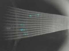
Photo 1 . Pulse #202. Only the experimental points as filmed (including the perspective error). Point number 1 can be seen very weak at right in this original image.
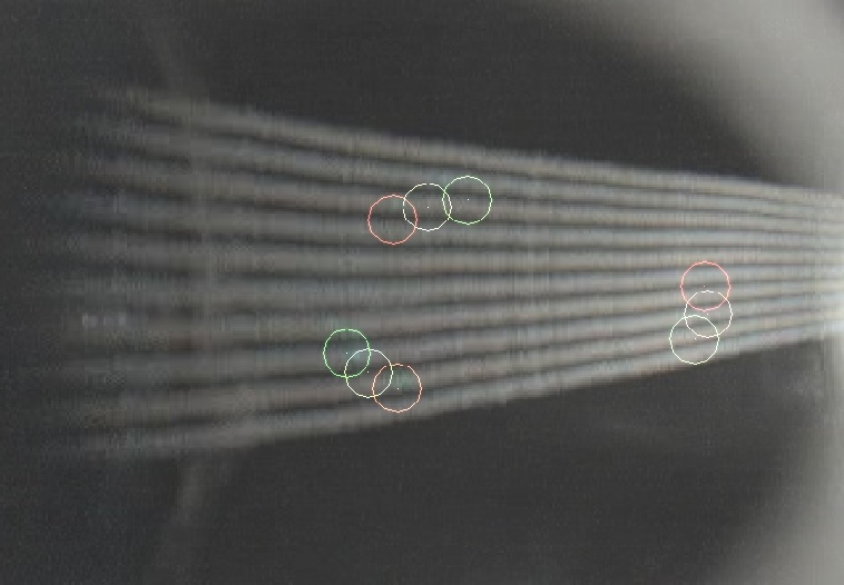
Image 2 . Pulse #198. Experimental points + theoretical for pulse #198. The points are obtained at 84V acceleration voltage so they are weaker than in Image 1. The e-gun is located 2.3 mm higer so to obtain a smaller surface. The simulation is obtained moving the e-gun vertically the real distance with respect the pulse #202 . Here there is a small deviation as a result of measurement errors, code inaccuracies, differences between model and real stellarator or others.
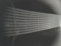
Photo 2 . Pulse #198. Only the experimental points as filmed. (including the perspective error). Five very faint points can be seen .
Image 3. Pulse #198. Poloidal
projections of e-beam on the emission poloidal plane. Clearly the 4th turn
collide with the back of the big e-gun (14mm diam.) but not on the small e-gun.
Date of publication 25-08-2006.